Backlight module and liquid crystal display module

A backlight module and backplane technology, which is applied in optics, nonlinear optics, instruments, etc., can solve the problems of the support structure losing the height of the support cavity, the deformation of the support structure, and the deformation cannot be recovered, so as to improve the quality, height and The effect of small size and not easy to deform

Inactive Publication Date: 2019-04-16
HUIZHOU CHINA STAR OPTOELECTRONICS TECHNOLOGY CO LTD
View PDF4 Cites 4 Cited by
  • Summary
  • Abstract
  • Description
  • Claims
  • Application Information

AI Technical Summary

Problems solved by technology

In addition, another function of the support structure is the support function. During the use of the backlight, the support structure needs to be able to maintain its original shape when it withstands a certain ambient temperature and a certain external force. However, the current support structure often encounters The reliability problem is that the temperature in the backlight cavity increases when the LED is working, or the ambient temperature is too high during transportation, or a certain deformation of the module during transportation will cause deformation of the supporting structure. At this time, the supporting structure will lose its support. function of cavity height, and its deformation is irreversible

Method used


Image

  • Backlight module and liquid crystal display module
  • Backlight module and liquid crystal display module
  • Backlight module and liquid crystal display module

Examples


Embodiment Construction

[0024] In order to further illustrate the technical means adopted by the present invention and its effects, the following describes in detail in conjunction with preferred embodiments of the present invention and accompanying drawings.

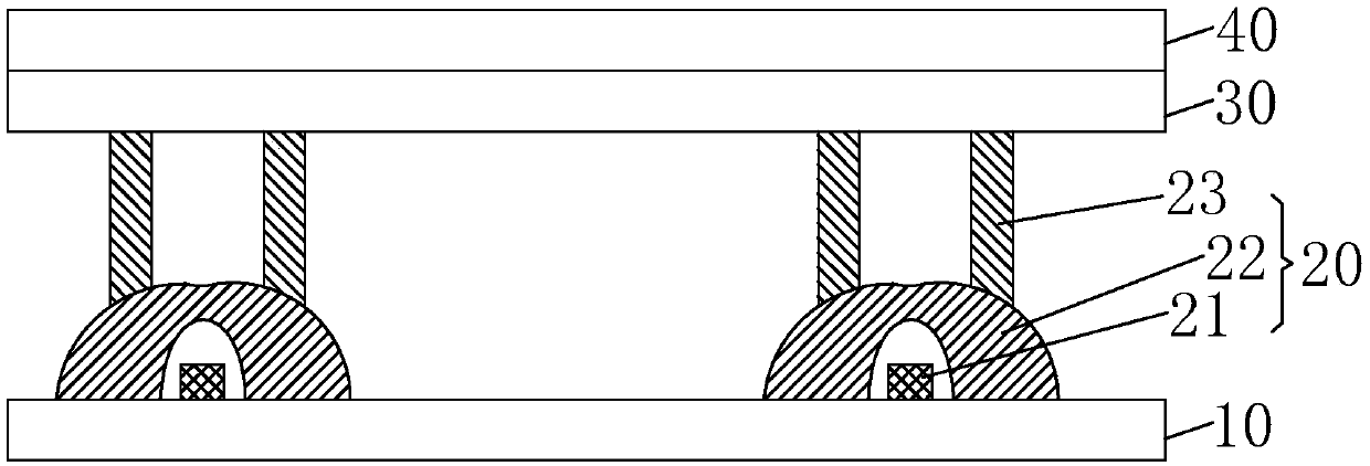
[0025] see figure 2 , the present invention provides a backlight module, comprising: a backplane 10, a plurality of light-emitting units 20 arranged at intervals on the backplane 10, and a diffusion plate 30 arranged on the light-emitting units 20;

[0026] The light emitting unit 20 includes a light emitting diode 21 , an LED lens 22 covering the light emitting diode 21 and at least one supporting structure 23 disposed on the LED lens 22 .

[0027] Specifically, the support structure 23 is located on the top of the LED lens 22 away from the light emitting diode 21 ; the light emitted by the light emitting diode 21 exits from the side of the LED lens 22 .

[0028] It should be noted that, in the light emitting unit 20 of the present inventio...


PUM


Abstract

The invention provides a backlight module and a liquid crystal display module. The backlight module comprises a back plate, a plurality of light emitting units arranged on the back plate at intervals,and a diffusing plate arranged on the light emitting units. Each light emitting unit comprises a light emitting diode, an LED lens which covers the light emitting diode and at least one support structure arranged on the LED lens, wherein the support structure and the LED lens support the height of a cavity together. The support structure provided by the invention has smaller height and size thana support structure in the prior art, and is not easy to deform. Due to the LED lenses, most of lights emitted by the light emitting diodes are centralizedly emitted out from the sides of the LED lenses. Since the support structures are located above the LED lenses, lights are not blocked, and shadows on the diffusing plate are avoided. The light emitting quality of the backlight module is improved.

Description

technical field [0001] The invention relates to the field of display technology, in particular to a backlight module and a liquid crystal display module. Background technique [0002] Thin Film Transistor (TFT) is the main driving element in current Liquid Crystal Display (LCD) and Active Matrix Organic Light-Emitting Diode (AMOLED). It is related to the display performance of the flat panel display device. [0003] Most of the liquid crystal displays currently on the market are backlight liquid crystal displays, which include a liquid crystal display panel and a backlight module. The working principle of the liquid crystal display panel is to pour liquid crystal molecules between the thin film transistor array substrate (ThinFilm Transistor Array Substrate, TFT Array Substrate) and the color filter (ColorFilter, CF) substrate, and apply pixel voltage on the two substrates respectively. and the common voltage, through the electric field formed between the pixel voltage and...

Claims


Application Information

Patent Timeline
IPC IPC(8): G02F1/13357
CPCG02F1/133603G02F1/133606G02F1/133608G02F1/133607
Inventor 付琳琳苏赞加常建宇丘永元俞刚罗柱平
Owner HUIZHOU CHINA STAR OPTOELECTRONICS TECHNOLOGY CO LTD
Why Eureka
Try Eureka