Motor driven equipment

A technology of motor drive and equipment, applied in the direction of electric components, electrical components, electromechanical devices, etc., can solve the problems of platform controller complexity and cost rise, and achieve the effects of decoupling, drive capacity growth, and cost reduction

Inactive Publication Date: 2014-04-02
肖俊东
View PDF3 Cites 3 Cited by
  • Summary
  • Abstract
  • Description
  • Claims
  • Application Information

AI Technical Summary

Problems solved by technology

This not only makes the platform controller more complicated, but also requires a dedicated control structure for decoupling control, which increases the cost, and often cannot be controlled by a general-purpose controller, requiring special customization. These factors restrict this multi-motor-driven platform. Applications

Method used


Image

  • Motor driven equipment
  • Motor driven equipment
  • Motor driven equipment

Examples


Embodiment Construction

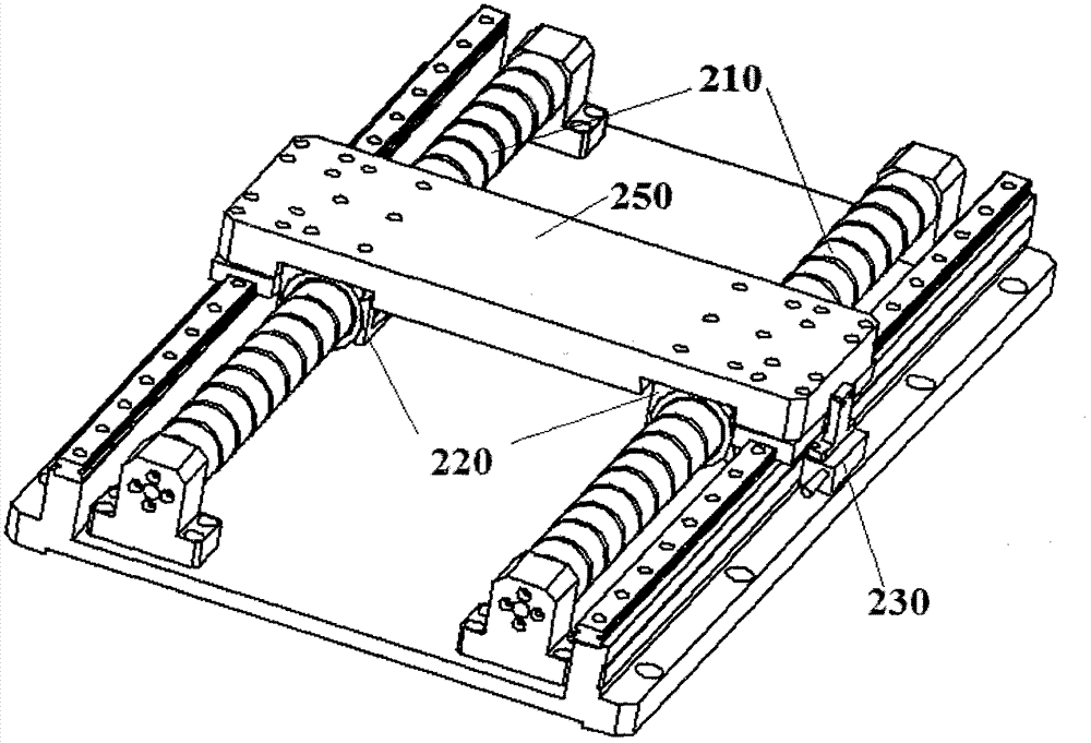
[0047] Refer to the attached figure 2 , 4 , 5. Describe in detail the embodiment of the motor-driven device according to the present invention.

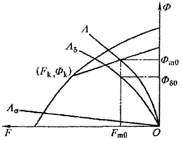
[0048] The multi-motor working platform proposed by the present invention can be compared with figure 2 are basically the same, but in motor design, the present invention adopts the design method of saturated magnetic field, specifically, the operating point of the motor is selected in the saturation region of the permanent magnet, such as Figure 5 Point B shown.

[0049] Since the motor works in the saturation region, even if there is a relatively large change and deviation in the operating point, it will not have a significant impact on the performance of the motor, so that it can well solve the interference of motor assembly, installation errors, work, and environmental temperature changes. Factors affect the performance of each motor. When multiple motors working at the same time are connected in series, their working perfo...


PUM


Abstract

The invention provides motor driven equipment. The motor driven equipment comprises magnetic axis components, at least two coil components and a connecting piece, wherein the magnetic axis components comprise a plurality of permanent magnets which are sequentially arrayed in preset magnetic axis extension directions; the coil components form permanent magnet linear motors with the magnetic axis components; air gaps are formed between the coil components and the magnetic axis components; and the connecting piece connects the at least two coil components and therefore is driven jointly by the at least two coil components. The motor driven equipment is characterized in that a ratio hm/delta of the length hm of each permanent magnet in a magnetizing direction of the permanent magnet to the length delta of each air gap is set in a basically even saturation zone of a relation curve of a ratio B delta/Br of air gap flux density B delta to residual flux density Br of each permanent magnet with the change of hm/delta. Therefore, the problem that the linear motors cannot operate consistently and synchronously due to the difference of the permanent magnets of the linear motors is avoided.

Description

technical field [0001] The present invention relates to motor driven equipment. Background technique [0002] Motor-driven equipment is used in a wide variety of applications. At present, many motor platforms are driven by linear motors. [0003] There are many types of linear motors. Here, an iron-core (air core) cylindrical linear motor is taken as an example for description. [0004] The structure of the ironless (air core) cylindrical linear motor is very simple. figure 1 is a schematic diagram of an ironless (air core) cylindrical linear motor. Such as figure 1 As shown, it mainly consists of two parts, a magnetic shaft assembly 110 and a cylindrical winding coil assembly 120 . The magnetic shaft assembly 110 includes a plurality of permanent magnets 115 . A plurality of permanent magnets 115 are arranged in sequence along a predetermined extending direction of the magnetic axis. During operation, the coil assembly 120 can move along the direction in which the m...

Claims


Application Information

Patent Timeline
Patent Type & Authority Applications(China)
IPC IPC(8): H02K41/02
Inventor 肖俊东
Owner 肖俊东
Why Eureka
Try Eureka