Droop control technology-based parallel inverter decoupling control method

A technology of decoupling control and control technology, which is applied in the field of decoupling control of parallel inverters based on droop control technology, which can solve the problem that the actual power cannot be equally divided, and achieve the effect of maintaining stability

Inactive Publication Date: 2014-04-02
XI AN JIAOTONG UNIV
View PDF3 Cites 14 Cited by
  • Summary
  • Abstract
  • Description
  • Claims
  • Application Information

AI Technical Summary

Problems solved by technology

Therefore, even if the virtual power is equally divided, the actual power cannot be equally divided, that is, the virtual power is not equivalent to the actual power.

Method used


Image

  • Droop control technology-based parallel inverter decoupling control method
  • Droop control technology-based parallel inverter decoupling control method
  • Droop control technology-based parallel inverter decoupling control method

Examples


Embodiment Construction

[0058] The present invention will be described in detail below in conjunction with the accompanying drawings.

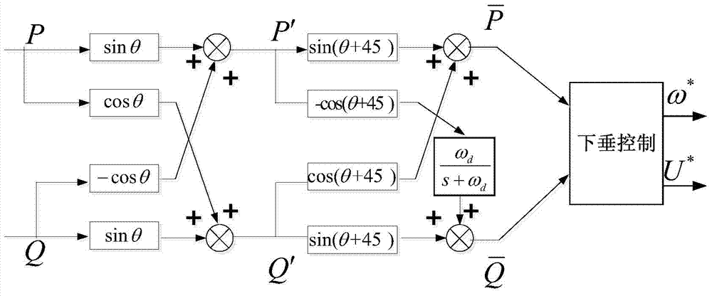
[0059] In order to solve the power control coupling problem caused by the impedance of the transmission line in the microgrid and parallel UPS system, the present invention proposes a decoupling control method for parallel inverters based on droop control technology. The actual power is rotated in two steps, and a decoupling low-pass filter is added to block the coupling path to achieve control decoupling, and the power after rotation is equivalent to the actual power. It specifically includes the following steps, such as figure 1 Shown:

[0060] 1) Measure the active power P output by the nth inverter (the subscript n is omitted in the following formula) inst and reactive power Q inst ;

[0061] 2) For the active power P inst and reactive power Q inst Carry out low-pass filtering respectively (filter out the high-frequency interference signal of the measured p...


PUM


Abstract

The invention provides a droop control technology-based parallel inverter decoupling control method. The method comprises the following steps of performing two rotation transformation steps on actual power, and adding a decoupled low-pass filter to block a coupling path. According to the method, active and reactive control can be decoupled, and influence on power sharing is avoided.

Description

technical field [0001] The invention relates to the field of wireless parallel control of inverters, in particular to a decoupling control method for parallel inverters based on droop control technology applied to UPS parallel power supply systems, distributed power generation and micro-grid systems. Background technique [0002] Droop control is a mainstream inverter parallel control method that does not require communication lines. In a parallel system with multiple inverters, according to KCL and KVL, for any nth inverter, its output power can be expressed by formula (1). [0003] [0004] From formula (1), it can be obtained that the reactive power is proportional to the voltage amplitude difference, and the active power is proportional to the voltage phase difference. Considering that the change of frequency can change the phase dynamically, so in the control, the reference value of output voltage amplitude and frequency can be generated by establishing the relation...

Claims


Application Information

Patent Timeline
Patent Type & Authority Applications(China)
IPC IPC(8): H02M7/493
Inventor 游致远刘进军张轩武腾
Owner XI AN JIAOTONG UNIV
Why Eureka
Try Eureka