In-depth extracting method of three-viewpoint stereoscopic video restrained by time-space domain

A technology for stereoscopic video and depth extraction, applied in stereoscopic systems, image data processing, instruments, etc.

Active Publication Date: 2014-04-02
SHANGHAI JIAO TONG UNIV
4 Cites 28 Cited by

AI-Extracted Technical Summary

Problems solved by technology

Therefore, the method is limited to depth estimation of sta...

Method used

[0204] The fourth step is to modify the energy function using the time-domain consistency constraint that the disparity map satisfies in the time domain and optimize it to eliminate jitter. The time domain consistency means that the corresponding matching points in the time domain point to the same spatial point, that is, they should have smoothly changing depth information.
[0224] Utilize the Middlebury stereoscopic image library to do experiments, and verify the effectiveness of the present invention for space domain constraints by comparing the error parallax rates of each stage. Experimental Results Figure 4 shows some experi...

Abstract

The invention discloses an in-depth extracting method of a three-viewpoint stereoscopic video restrained by time-space domain. The method comprises the steps of searching an optimal matching point from left and right viewpoint images by aiming at a center viewpoint image, optimizing a parallax error estimation process based on an energy function by adopting a BP algorithm and a plane fusion method, adopting three-view parallax error and shielding information iterative optimization, establishing a time domain parallax error constraint relation between adjacent frames through an optical flow method, defining the confidence coefficient of the optical flow method, so as to restrain parallax error sequence time domain hopping, eliminating errors caused by parallax error value quantification by utilizing binomial sub pixel estimation and bilateral filters, obtaining the parallax error of sub pixel accuracy, quantizing the obtained parallax error, and then obtaining a final in-depth sequence. Compared with the prior art in which constraint is performed by adopting a single frame only, the method has the advantages that the method searches multi-reference frame optical flow, and can better avoid the propagation of space domain error on time domain, thereby being capable of obtaining a continuous and accurate in-depth image sequence on time-space domain through a three-viewpoint image.

Application Domain

Image analysisSteroscopic systems

Technology Topic

Energy basedParallax +13

Image

  • In-depth extracting method of three-viewpoint stereoscopic video restrained by time-space domain
  • In-depth extracting method of three-viewpoint stereoscopic video restrained by time-space domain
  • In-depth extracting method of three-viewpoint stereoscopic video restrained by time-space domain

Examples

  • Experimental program(1)

Example Embodiment

[0115] The present invention will be described in detail below in conjunction with specific embodiments. The following examples will help those skilled in the art to further understand the present invention, but do not limit the present invention in any form. It should be pointed out that for those of ordinary skill in the art, a number of modifications and improvements can be made without departing from the concept of the present invention. These all belong to the protection scope of the present invention.
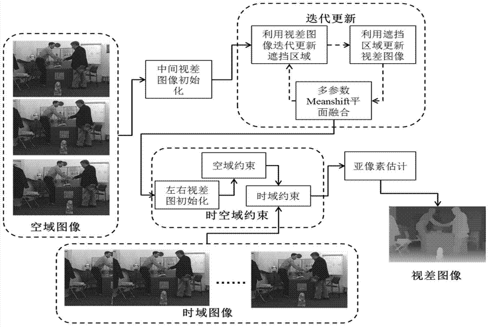
[0116] Such as figure 1 As shown, the three-view depth sequence estimation method of the present invention includes the initialization of the middle-view disparity map, the iterative update of the disparity map and the occlusion image, the initialization of the left and right disparity images, the spatio-temporal constraints, and the sub-pixel estimation.
[0117] In the first step, for the intermediate viewpoint image I t,L , Calculate the initial matching energy distribution, use BP algorithm to optimize the energy function, and add Meanshift image segmentation to achieve plane constraints, and obtain the depth image D t,L.
[0118] The initialization process of the intermediate viewpoint depth image is as follows:
[0119] 1) Calculate the initial energy distribution
[0120] For the intermediate viewpoint image I t,C Pixel x c =(x,y) and given parallax d x , Which corresponds to the pixel x of the right viewpoint image R X R =(x,y-d x ), therefore, the matching cost is:
[0121] Cost C , R ( x C , d x ) = τ · | I t , C ( x C ) - I t , R ( x R ) | 3 + ( 1 - τ ) · C census ( I t , C ( x C ) , I t , R ( x R ) )
[0122] Where the first term represents x c With x R The average value of the absolute difference of RGB, the second item C census (I t, C (x C ), I t, R (x R )) means x c With x R The local structural similarity. For C census (I t,C (x C )I t,R (x R )) in pixels x c For example, such as figure 2 As shown, first convert the color RBG image into a grayscale image, the conversion formula is Gray=0.299xR+0.587xG+0.114×B and then convert the grayscale information into structural information. The specific way is to change x c Compare the size with its 5×5 neighborhood pixels, if the neighborhood pixel ratio x c If the gray value is large, set it to 1, otherwise set it to 0, and get a 25-bit binary string accordingly. Finally, C census (I t, C (x C ), I t, R (x R )) represents the Hamming distance of two binary strings.
[0123] Generally speaking, the value range of τ is: [0.3,0.7]. It is in the left view image I t,L The corresponding pixel in is X L =(x, y+d x ), Cost C, L (x C , D x ) Has the same as COSt C, R (X C , D x ) Similar definition.
[0124] 2) Define the initial energy function
[0125] The initial energy function is defined as:
[0126] E t , C init ( D t , C ; Cost C , R , Cost C , L ) = X x c min ( ρ ( Cost C , R ( x C , d x ) ) , ρ ( Cost C , L ( x C , d x ) ) ) + E t , C s ( x C ) - - - ( 1 )
[0127] Where P(C)=-ln((1-e d )exp(-C/σ d )+e d ) Is a truncation function robust to noise, It is a smoothing term function that is convenient to use BP algorithm optimization, and it is defined as:
[0128] E t , C s ( x C ) = X x c X y c A N ( x c ) ω s · λ ( x C , y C ) · min ( | D t , C ( x C ) - D t , C ( y C ) | , η s )
[0129] Where λ(x C , Y C )=ε/(ε+||I t,C (x C )-I t,C (y C )|| 2 ), N(x c ) Means pixel x c Neighborhood, ‖·|| 2 It is 2 norm. Finally, use the BP algorithm to optimize the energy function (1) to obtain the initial disparity map
[0130] ω s The value range is: [0.1,0.4], e d The value of is 0.01, σ d The value of is 4.0, η s The value of is 2, and the value range of ε is [5.0,15.0].
[0131] 3) BP optimization
[0132] The first item in formula (1) is a data item, usually expressed as D d (f p ), which represents the label defining the pixel p (here, the disparity) is f p The cost of the second term is the smoothing term, denoted as D s (f p ,f q ), which means that the labels of two adjacent pixels p and q are respectively defined as f p And f q The cost of BP algorithm is realized through message transmission. definition It is the message that node p transmits to neighboring node q in the i-th iteration. Every message is a Dimensional vector. The calculation of each element in is as follows:
[0133] m pq i ( f q ) = min f p ( D d ( f p ) + D s ( f p , f q ) + X s A N ( p ) \ q m sp i - 1 ( f p ) )
[0134] In the formula, N(p) represents the neighborhood of pixel p. s is the point not including q in the neighborhood. In the specific solution , For every possible f q , Calculated separately at each f p The value of the next message, and then take all f p Find the smallest assignment in the message to the corresponding Therefore, two cycles are required in the calculation.
[0135] After T times (the value of T in the experiment is 3-6 times) iterations, the confidence vector b is calculated for each pixel q (f q ), each confidence vector is also d max -d min Dimensional. The calculation is as follows:
[0136] b q ( f q ) = D d ( f q ) + X p A N ( q ) m pq T ( f q ) )
[0137] Finally for each pixel, in all b q (f q ) To find out so that b q The smallest component corresponds to It is the disparity value of the pixel. That is, the pixel corresponds to The energy value.
[0138] 4) Plane constraints based on Meanshift image segmentation
[0139] (A) Use Meanshift to compare I t, C Perform image segmentation and get the segmentation result Among them, I is the number of division planes.
[0140] (B) For each plane obtained by segmentation use Fit the initial disparity value corresponding to the area in the 3D plane in space, that is: for the plane and Its depth value is determined by d x =a i x+b i y+c i Is given, where [a i b i c i ] Is the 3D plane coefficient equation. The fitting process is as follows:
[0141] [1] For the disparity map optimized by the BP algorithm First assume The corresponding 3D plane is parallel to the imaging plane, that is, assuming a i = 0, b i =0, by and area corresponding Calculate the minimum energy that is c in formula (1) i , And record the energy value of the area.
[0142] [2] Assumption The corresponding 3D plane intersects the imaging plane, and the 3D plane coefficient is calculated using the least square method. Use the average coefficient to calculate the fitting plane d′ x. For each pixel in the fitted 3D plane, calculate its value in [d′ x -m, d′ x +m] The minimum cost parallax in the range, update the new 3D fitting plane accordingly, and perform the least square calculation to update the 3D plane coefficients, and repeat this process until the 3D plane coefficients converge. Finally, calculate the energy corresponding to the remaining planes.
[0143] The value range of m is [2,5].
[0144] [3] When the fitting plane in [2] satisfies the condition, use the 3D plane coefficients calculated in [2] to update the corresponding disparity of the pixels in the plane, otherwise, use the 3D plane coefficients calculated in [1] to update the in-plane The parallax of each pixel to get the updated parallax image
[0145] The condition is: I. Plane energy is less than [1] mid-plane energy.
[0146] II. The point rate InlierRatio in the fitting plane is greater than η r.
[0147] The η r The value range of is [0.3,0.6]. The InlierRatio is:
[0148] InlierRatio = X x c A S t , C i f ( | a i x + b i y + c i - D t , C ( x c ) | ) sum ( x c A S t , C i )
[0149] The function f(|a i x+b i y+c i -D t, C (x c )|) is:
[0150] f ( x ) = 1 , ifx ( d max - d min ) / 40 0 , otherwise
[0151] Said Representation area The number of pixels within.
[0152] The second step is to use the obtained initial disparity map to iteratively update the disparity and the occlusion area. The iterative update of parallax and occlusion is implemented as follows:
[0153] 1) According to the parallax image extracted in the first step Calculate the occlusion information of the left and right views.
[0154] The calculation process of occlusion information is: use The middle viewpoint is projected to the left and right viewpoints, and the hole that appears after the projection becomes the occlusion information of the viewpoint in the middle viewpoint. For example, the occlusion area of ​​the right view in the middle view is represented as a binary image O R,C (X R ), where O R, C (X R )=1 means that the right view is visible in the middle view, O R,C (X R )=0 means that the right view is not visible in the middle view. O L, C (x L ) Has the same definition.
[0155] 2) Modify the initial matching cost function as:
[0156] Cost C , R v ( x C , d x ) = Cost C , R ( x C , d x ) + ρ v · O R , C ( x R )
[0157] Has a similar definition.
[0158] Said p v The value is 4.0.
[0159] 3) Using the known disparity, find the occlusion area of ​​the middle view in the left and right views. C, R , O C, L. Where O C, R (X R )=1 means x in the middle view C Pixels are visible in the right view, O C,R (X R )=0 means x in the middle view C The pixels are not visible in the right view. O C,R (X L ) Has the same definition. Blocking area O C,R , O C,L The energy function of is defined as follows:
[0160] E t , C d , v ( O C , L O C , R ; D t , C ) = X x C ( O C , L ( x C ) O C , R ( x C ) · β + ( 1 - O C , R ( x C ) ) ( 1 + O C , L ( x C ) ) .
[0161] ρ ( Cost C , R v ( x C , D t , C ( x C ) ) ) ( 1 - O C , L ( x C ) ) ( 1 + O C , R ( x C ) ) · ρ ( Cost C , L v ( x C , D t , C ( x C ) ) ) )
[0162] The value of β is 3.5. Where P(C)=-ln((1-e d )exp(-C/σ d )+e d ) Is a truncated function robust to noise. β is a penalty term introduced to prevent all pixels in the occluded image from being estimated as an occluded area, and the value is 10.0 in the experiment.
[0163] 4) Calculate the initial information W of the intermediate view occlusion L (X C ),W R (X C ).
[0164] The specific calculation process is as follows:
[0165] For a given parallax X C Map to x L , For mapping to the same x L X C , Sort them according to their disparity size (including the sign), the x with the largest disparity C Will be considered unobstructed (W L (x C )=0), and the rest will be regarded as occlusion (W L (x C )=1). W R (x C The calculation process of) is similar.
[0166] 5) For O C,L With O C,R Violation of W L (x C ) And W R (x C The penalty function of) is:
[0167] P t , C ( O C , L , O C , R ; W L , W R ) = X x C β ω ( | O C , L ( x C ) - W L ( x C ) | + | O C , R ( x C ) - W R ( x C ) | )
[0168] The β ω The value of is 1.5.
[0169] 6) The final occlusion image energy function of the intermediate view is defined as:
[0170] E O ( O C , L , O C , R ; D t , C ) = X x C E t , C d , v + P t , C + X y c A N ( x c ) β o · ( | O C , L ( x C ) - O C , L ( y C ) | + | O C , R ( x C ) - O C , R ( y C ) | ) - - - ( 2 )
[0171] The third term is the smooth term function of the occluded area. Where P t,C Is the penalty term introduced, namely O C,L (x C ) And O C,R The initial reference image.
[0172] The β O The value of is 10.0.
[0173] 7) Use the BP algorithm to optimize the energy function, which is formula (2), to obtain the middle view occlusion image O C,L , O C,R.
[0174] 8) According to the middle view occlusion image obtained according to the process of 1)-7), the matching energy function of the middle view is defined as:
[0175] E t , C d , v ( D t , C ; Cost C , R v , Cost C , L v ) = X x C u ( x C ) · ( O C , L ( x C ) O C , R ) ( x C ) β + ( 1 - O C , R ( x C ) ) ( 1 + O C , L ( x C ) ) · ρ ( Cost C , R v ( x C , d x ) ) + ( 1 - O C , L ( x C ) ) ( 1 + O C , R ( x C ) ) · ρ ( Cost C , L v ( x C , d x ) ) ) + E t , C s ( x C ) - - - ( 3 )
[0176] 9) Use the BP algorithm to optimize the matching energy function (3) to retrieve the corrected initial disparity image
[0177] 10) Meanshift plane fusion based on multiple parameters
[0178] The implementation of plane fusion technology is as follows:
[0179] In order to ensure the robustness of the present invention against Meanshift segmentation errors, by changing the Meanshift segmentation parameters, n multiple segmentation results (5-6) are obtained. Therefore, each pixel can obtain n potential disparity values ​​(Candidate), and finally, use these potential disparity values ​​to optimize the energy function again, namely formula (3), to obtain the final disparity image of this step It should be noted here that when using BP optimization, the tag value no longer belongs to [d min , D max ], but n potential disparity values ​​fitted by n segmentation results, and the value range of n is [3,6].
[0180] 11) Repeat steps 1)-10) 1-2 times, continuously update the occlusion information, O C,L , O C,R , O R,C And O L,C And parallax images
[0181] 12) Use the latest occlusion information to realize the left and right disparity map with Initialization.
[0182] The initialization of the left and right disparity map is implemented as follows:
[0183] The matching cost function of the right view is:
[0184] Cost R , C v ( x R , d x ) = Cost R , C ( x R , d x ) + p v · O C , R ( x C )
[0185] The corresponding energy function of the right view is:
[0186] E t , R d , v ( D t , R ) = X x C ( O R , C ( x R ) · β + ( 1 - O R , C ( x R ) ) · ρ ( Cost R , C v ( x R , d x ) ) + E t , R s ( x R ) - - - ( 4 )
[0187] Use the BP algorithm to optimize the energy function (4) to obtain the right disparity map Left disparity map The process of obtaining is similar. Finally, use the multi-parameter Meanshift plane fusion to calculate the left and right disparity map
[0188] The third step is to use the spatial consistency constraints that the three disparity maps should satisfy to further modify the energy function and perform iterative optimization. The spatial consistency is: for example, a certain pixel x in the right picture R Intermediate view x C Should have the same disparity value.
[0189] The concrete realization of space constraint iterative optimization is as follows:
[0190] 1) After introducing spatial consistency constraints, the matching cost function of the middle view and the right view is defined as:
[0191] Cost C , R v , s ( x C , d x ) = Cost C , R v ( x C , d x ) + ρ v · min ( s · | d x - D t , R plane ′ ( x R ) | , T S )
[0192] The value of s is 30/(d min -d max ),d min Is the minimum parallax, d max Is the maximum parallax. T s The value is 4.0. Has a similar definition. By using with Replace (3) in with The matching energy function of the middle view is modified to:
[0193] E t , C d , v , s ( D t , C ; Cost C , R v , S , Cost C , L v , s ) = E t , C d , v ( D t , C ; Cost C , R v , s , Cost C , L v ) - - - ( 5 )
[0194] Finally, use the BP algorithm to optimize the function (5) to obtain the intermediate disparity map
[0195] 2) Use the obtained intermediate disparity map Modify the energy function (2) to:
[0196] E O ( O C , L , O C , R ; D t , C spatial ) = X x C E t , C d , v , s + P t , C + X y c A N ( x c ) β o · ( | O C , L ( x C ) - O C , L ( y C ) | + | O C , R ( x C ) - O C , R ( y C ) | ) - - - ( 6 )
[0197] Use the BP algorithm to optimize the function (6) to get the updated O C,L , O C,R , And update O by mapping the middle viewpoint again R,C And O L,C.
[0198] 3) Using the obtained occlusion information, modify the matching cost function of the right viewpoint as:
[0199] Cost R , C v , s ( x R , d x ) = Cost R , C v ( x R , d x ) + p v · min ( s · | d x - D t , C spatial ( x C ) | , T s )
[0200] Modify the energy function of the right viewpoint as:
[0201] E t , R d , v ( D t , R spatial ) = X x C ( O R , C ( x R ) · β + ( 1 - O R , C ( x R ) ) · ρ ( Cost R , C v . s ( x R , d x ) ) + E t , R s ( x R ) - - - ( 7 )
[0202] Optimized by BP algorithm (7) to get the updated right-view disparity Left viewpoint parallax The process of obtaining is similar to the right viewpoint.
[0203] 4) Repeat steps 1)-3) 1-2 times, continuously update the occlusion information and the parallax of each viewpoint, and finally get three consistent parallaxes in the spatial domain with
[0204] The fourth step is to use the time domain consistency constraint that the disparity map satisfies in the time domain to correct and optimize the energy function to eliminate jitter. The time domain consistency means that the corresponding matching points in the time domain point to the same spatial point, that is, they should have smoothly changing depth information.
[0205] The time domain consistency optimization includes the following steps:
[0206] 1) Find the optical flow from the tth frame to the t′th frame That is: the corresponding point of the pixel x in the tth frame in the t′th frame can be determined by x ′ = x + P I t , I t ′ ( x ) Figure out.
[0207] 2) The confidence of optical flow method is defined as:
[0208] C t , t ′ ( x ) = exp ( - | | x - x ′ ′ | | σ r ) · exp ( - | | I t ( x ) - I t ′ ( x ′ ) | | σ c )
[0209] Among them, x′′ is the pixel position where x′ is back projected to the t-th frame. ||x-x′′|| represents the Euclidean distance of two pixels on the image, ||I t (x)-I t′ (x')|| represents the 2-norm of the difference between the RGB values ​​of the pixel. The σ r The value is 5, σ c The value is 10.
[0210] 3) The matching cost function considering the time domain consistency constraint from the tth frame to the t′th frame is defined as:
[0211] Cost C tem ( x C , d x ) = min ( Cost C , R ( x C , d x ) , Cost C , L ( x C , d x ) ) + p t · X t ′ C t , t ′ ( x c ) · min ( s · | d x - D t ′ , C spatial ( x c ′ ) | 2 , T t )
[0212] Said p t The value is 1, T t The value is 9. The defined energy function is:
[0213] E t . C tem ( D t , C tem ) = X x c ρ ( Cost C tem ) + E t , C s ( x C ) - - - ( 8 )
[0214] Use the BP algorithm to optimize the function (8) to obtain a depth image that is consistent in the temporal and spatial domains
[0215] The fifth step is to use binomial sub-pixel estimation and joint bilateral filtering to eliminate errors caused by disparity map quantization.
[0216] The specific implementation of binomial sub-pixel estimation and joint bilateral filtering is as follows:
[0217] Use quadratic function to approximate the energy function distribution of pixel q, namely:
[0218] b q (x)=ax 2 +bx+C
[0219] Therefore, for the depth image D obtained by the fourth step t,C , For pixel q, its depth value d q The energy is b q (b q ). The sub-pixel disparity value can be calculated by the following formula:
[0220] d q sub = d q - b q ( d q + ) - b q ( d q - ) 2 X ( b q ( d q + ) + b q ( d q - ) - 2 X b q ( d q ) )
[0221] among them, Finally, perform joint bilateral filtering based on depth and color on sub-pixel depth images:
[0222] d q final = 1 Z ( q ) X p A N ( q ) e - | I t , C ( q ) - I t , C ( p ) | 3 X σ color X e - | d q sub - d p sub | σ disparity X d p sub
[0223] Among them, z(q) is the normalization factor: Z ( q ) = X p A N ( q ) e - I t , C ( q ) - I t , C ( p ) | 3 X σ color X e - | d q sub - d p sub | σ disparity , σ color The value is 2, σ disparity The value is 2, N(p) represents the neighborhood of pixel p.
[0224] The Middlebury stereo image library is used for experiments to verify the effectiveness of the present invention for spatial domain constraints by comparing the error disparity rates of various stages. Experimental results Figure 4 Part of the experimental results, experimental results Figure 5 The error parallax rate of each stage is listed, where the error parallax refers to the parallax where the absolute value of the difference between the experimental result and the real parallax is greater than 1 pixel. From the experimental results Figure 4 with 5 It can be seen that the present invention can effectively estimate the depth image, and the error disparity rate is kept at a low level, which shows that the algorithm can effectively deal with occlusion and homogeneity regions, and the plane fusion technology can maintain the robustness of the segmentation error results. Great and maintain sharp depth image edges.
[0225] Experiment with the multi-viewpoint video sequence provided by the Moving Picture Experts Group research group, Image 6 Shows the output results of the present invention at various stages, Figure 7 Shows the suppression effect on the time-domain transition of the depth sequence after the time domain constraint is added. The first line is the middle view, the second line is the disparity map sequence without time domain constraints, and the third line is the disparity map sequence with time domain constraints. .
[0226] The method of the present invention is aimed at the three-viewpoint stereo image sequence, by combining the occlusion area modeling between the viewpoints, the plane constraint based on the segmentation in the viewpoint, the spatial domain constraint, the time domain constraint, the belief propagation algorithm and the Markov random field. Three-view depth sequence information extraction under a unified iterative framework. The invention can accurately estimate the occlusion information when the camera baseline distance is large, and complete the estimation of the disparity sequence accordingly, and finally obtain the depth image sequence through the disparity quantization. The occlusion information, disparity information and spatiotemporal constraints between viewpoints are updated under a unified iterative framework. Because the wrong disparity value is difficult to obtain consistent support both in space and time, the probability of the energy function falling into a local minimum is greatly reduced in the optimization process of the BP algorithm. Compared with using only a single plane segmentation result, by using the multi-parameter plane segmentation result, the present invention is robust against segmentation errors; the optical flow confidence definition of the present invention makes it possible to maintain the optical flow error during time domain constraint optimization Robust. Compared with using only a single frame for constraint, the present invention searches for optical flow of multiple reference frames, which can well avoid the propagation of spatial errors in the time domain. Therefore, the present invention can obtain continuous and accurate depth image sequences in both time and space domains through three-viewpoint images, and can be widely used in 3D program production, image segmentation, video editing, virtual reality and other fields.
[0227] The specific embodiments of the present invention have been described above. It should be understood that the present invention is not limited to the above specific embodiments, and those skilled in the art can make various deformations or modifications within the scope of the claims, which does not affect the essence of the present invention.

PUM

no PUM

Description & Claims & Application Information

We can also present the details of the Description, Claims and Application information to help users get a comprehensive understanding of the technical details of the patent, such as background art, summary of invention, brief description of drawings, description of embodiments, and other original content. On the other hand, users can also determine the specific scope of protection of the technology through the list of claims; as well as understand the changes in the life cycle of the technology with the presentation of the patent timeline. Login to view more.
Why Eureka
Try Eureka