Synchronous detection method for TD-LTE (time division long term evolution) network optimized equipment

A technology of synchronous detection and network optimization, applied in the field of communication, can solve the problems of increasing the size of the chassis, the structure is not compact, and the equipment cannot work, and achieves the effect of reducing the requirements of real-time performance, compact structure and cost reduction.

Active Publication Date: 2014-04-02
WUHAN HONGXIN TELECOMM TECH CO LTD
View PDF4 Cites 13 Cited by
  • Summary
  • Abstract
  • Description
  • Claims
  • Application Information

AI Technical Summary

Problems solved by technology

[0004] At present, there are two main synchronization methods for TD-LTE network optimization equipment: GPS synchronization and demodulation synchronization. The GPS synchronization method first increases the system cost, especially the LTE modem is currently relatively expensive; the existing technology is used to form a final product At the same time, GPS or modem needs to be placed in the chassis, which will increase the size of the chassis, as well as increase the power supply and RF coupling connection, and the structure is not compact
Secondly, the installation location of the network optimization device must meet the requirements of GPS to be able to synchronize normally, so that it cannot be applied in some indoor coverage scenarios, and the device cannot work when the GPS cannot receive signals under certain harsh conditions; Solution The method of adjusting synchronization is mainly realized by using a modem with a TD-LTE baseband processing chip. After the modem couples a part of the input signal to complete the synchronization, it directly outputs the switching signal for the device to use.
At present, the cost of the existing TD-LTE baseband chip is relatively high, which also increases the system cost

Method used


Image

  • Synchronous detection method for TD-LTE (time division long term evolution) network optimized equipment
  • Synchronous detection method for TD-LTE (time division long term evolution) network optimized equipment
  • Synchronous detection method for TD-LTE (time division long term evolution) network optimized equipment

Examples


Embodiment Construction

[0034] The present invention will be described in further detail below with reference to the embodiments and the accompanying drawings, but the embodiments of the present invention are not limited thereto.

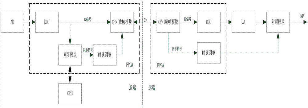
[0035] like figure 2 As shown, the hardware implemented by the embodiment of the present invention includes a near-end access unit (near-end) and a far-end radio frequency unit (far-end). On the downlink, the near-end access unit includes an AD conversion unit (AD), a near-end End FPGA, CPU; near end FPGA includes DDC module, synchronization module, near end CPRI framing module, near end delay adjustment module; far end radio frequency unit includes far end FPGA, DA conversion module, radio frequency module; far end FPGA includes far end FPGA End CPRI deframe module, remote delay adjustment module, DUC module;

[0036] The input end of the DDC module is connected to the output end of the AD conversion unit, and the output end of the DDC module is respectively connect...


PUM


Abstract

The invention provides a synchronous detection method for TD-LTE (time division long term evolution) network optimized equipment. The synchronizing with a base station is finished by fully using the hardware (mainly comprising an FPGA (field programmable gate array) and a CPU (central processing unit)) of the existing network optimized equipment. The method comprises the steps that a near end generates a synchronous switch signal according to an input signal and transmits the switch signal to each far end; each far end controls a radio frequency switch to realize uplink-downlink switching according to the switch signal. As the CPU is not a special signal processing chip, the CPU cannot realize real-time treatment under the condition of larger delay (time for calculating SSS once is at second level) and an LTE (long term evolution) semi-frame being 5ms long when massive data are processed. The method adopts an asynchronous calculation mode, so the demand on real-time property is reduced. The demand on the real-time property of the CPU is not high, a GPS (global positioning system) module and a modem do not need to be connected, the equipment cost is reduced, and the structure is more compact.

Description

[0001] technical field [0002] The invention belongs to the technical field of communication, and in particular relates to a synchronization detection method of a TD-LTE network optimization device. Background technique [0003] The TD-LTE system is a time division duplex mode, and the uplink and downlink share the same frequency band. Therefore, in order for the TD-LTE network optimization equipment to work normally, it must first obtain synchronization information from the base station signal. Perform accurate switching to ensure that the uplink and downlink signals can be fully amplified by the network optimization equipment. [0004] At present, there are two main synchronization methods for TD-LTE network optimization equipment: GPS synchronization and demodulation synchronization. The use of GPS synchronization method first increases the system cost, especially the current price of LTE modem is relatively expensive; When the GPS or modem needs to be placed in the...

Claims


Application Information

Patent Timeline
Patent Type & Authority Applications(China)
IPC IPC(8): H04W56/00
Inventor 艾锋张杰周巧玲江鹏
Owner WUHAN HONGXIN TELECOMM TECH CO LTD
Why Eureka
Try Eureka