
Sheathing tube capable of being adjusted to be bent

A sheath tube and bend adjustment technology, which is applied in the direction of the catheter, etc., can solve the problems of reduced flexibility of the elastic bending section, insufficient flexibility, affecting the flexibility of the sheath tube, etc., to ensure the connection strength and connection stability, and the structure of the traction mechanism is simple. Effect

Active Publication Date: 2014-04-09
ZHONGSHAN HOSPITAL FUDAN UNIV +1
View PDF10 Cites 22 Cited by
  • Summary
  • Abstract
  • Description
  • Claims
  • Application Information

AI Technical Summary

Problems solved by technology

Moreover, the fixed anchor is an elongated structure along the axial direction of the tube body, and the tube body is also provided with a developing ring at the far end relative to the fixed anchor, so that the length of the rigid section at the distal end of the tube body increases, and the compliance of the elastic bending section decreases. , when the distal end of the tubular body is bent to a certain angle, compared with the tubular body with a short rigid section, the deflection radius of the distal end of the tubular body with this structure is larger, which affects the flexibility of the sheath during advancement. In the body lumen of the space, if the deflection radius is large, there is not enough space for the sheath to bend

Method used


Image

  • Sheathing tube capable of being adjusted to be bent
  • Sheathing tube capable of being adjusted to be bent
  • Sheathing tube capable of being adjusted to be bent

Examples


Embodiment Construction

[0030] In order to have a clearer understanding of the technical features, purposes and effects of the present invention, the specific implementation manners of the present invention will now be described in detail with reference to the accompanying drawings.

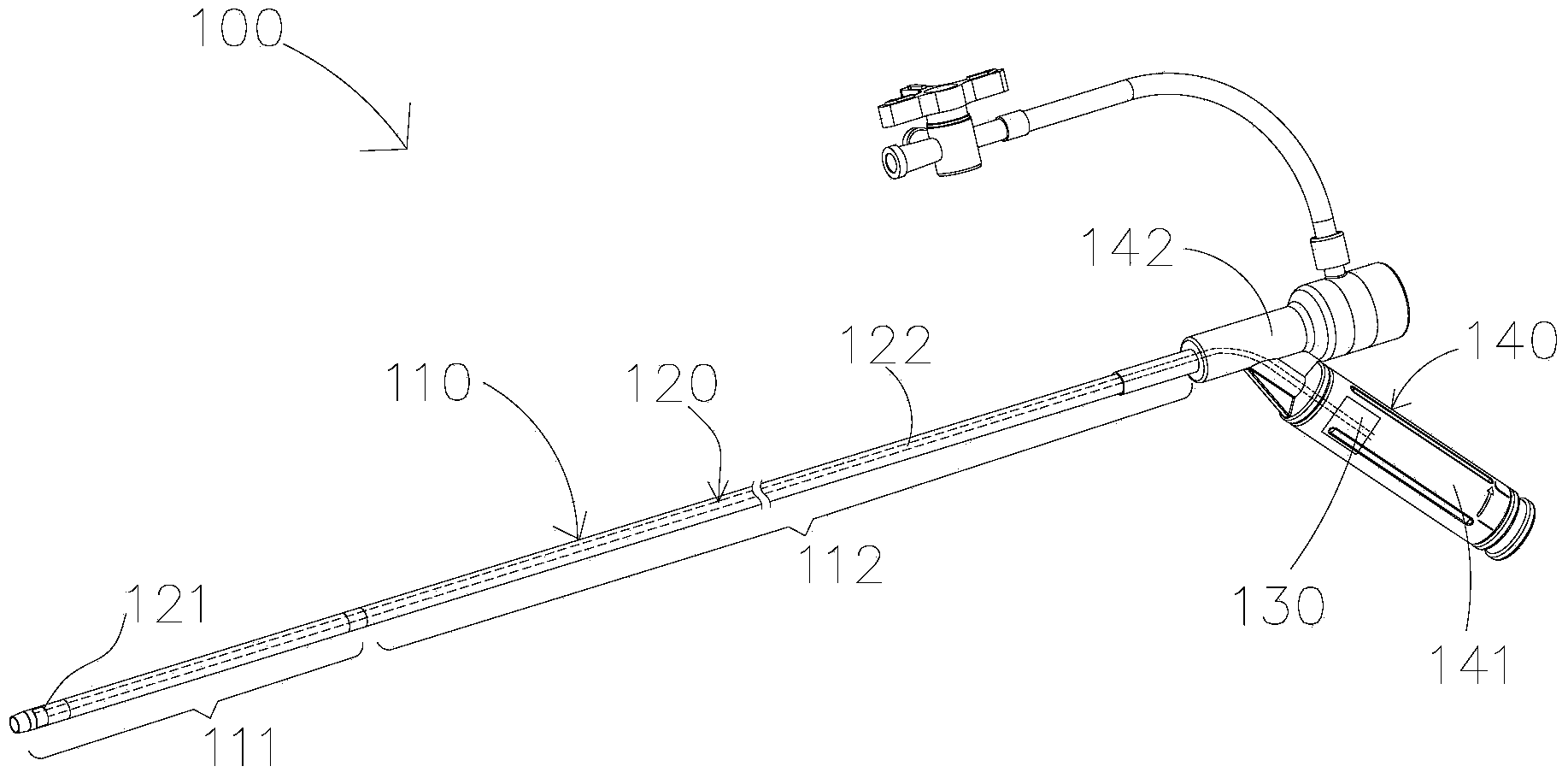
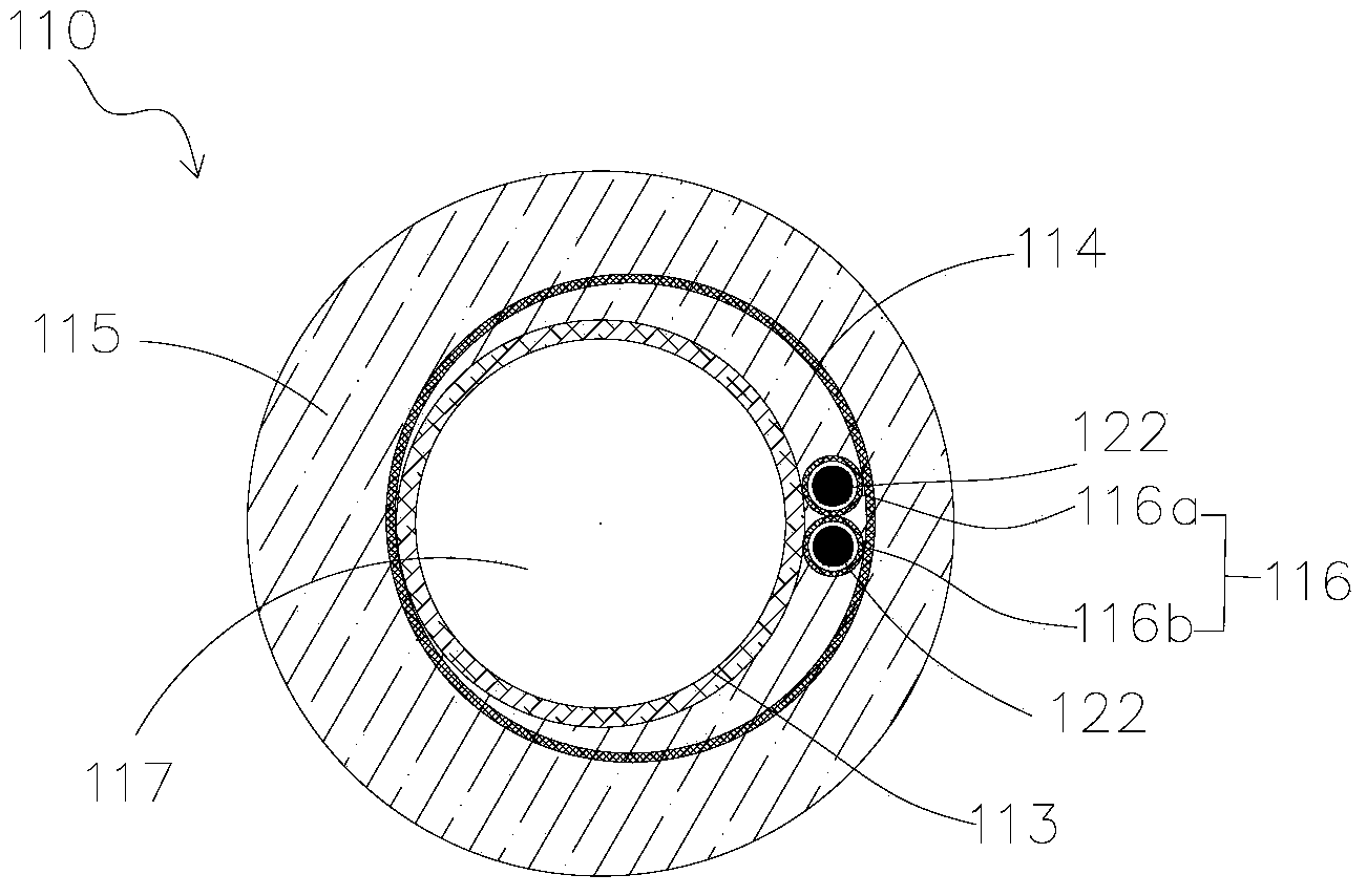
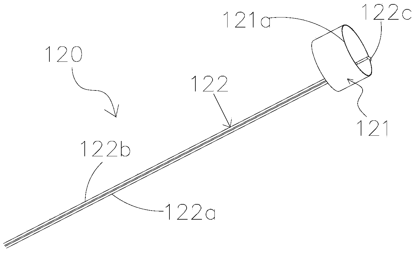
[0031] see Figure 1 to Figure 5 , the adjustable curved sheath tube 100 according to the first embodiment of the present invention includes a tube body 110 , a traction mechanism 120 , a fixed connection mechanism 130 and a handle 140 . The proximal end of the tube body 110 is fixedly connected to the handle 140 ; ​​the traction mechanism 120 is axially embedded in the side wall of the tube body 110 and connected to the fixed connection mechanism 130 located in the handle 140 near the proximal end of the tube body 110 .

[0032] The tubular body 110 includes a distal elastic section 111 and a proximal rigid section 112 with different elastic modulus in the axial direction, and the proximal rigid section 112 is fixedly ...


PUM


Abstract

The invention discloses a sheathing tube capable of being adjusted to be bent. The sheathing tube comprises a tube body, a traction mechanism and a fixed connecting mechanism. The traction mechanism comprises an anchoring ring and a traction wire. The anchoring ring is coaxially embedded into the far-end elastic section of the tube body. The traction wire is arranged in the side wall of the tube body and extends in the axial direction of the tube body, the traction wire comprises a first section and a second section which are connected with each other, the first section is connected with the fixed connecting mechanism near the near end of the tube body, and the second section hooks the anchoring ring. Due to the fact that the traction wire hooks the anchoring ring, the stress point between the anchoring ring and the traction wire is a hooking part, the connecting mode is similar to the flexible connection, and the connecting strength and the connecting stability between the anchoring ring and the traction wire can be guaranteed. In addition, the traction mechanism is simple in structure, components do not need to be additionally arranged,the structure does not need to be additionally improved, only the connecting mode of the traction wire and the anchoring ring needs to be changed, the size of the anchoring ring and the size of the traction wire do not need to be increased, and then the thickness of the side wall of the tube body cannot be influenced obviously.

Description

technical field [0001] The invention relates to the field of medical instruments, in particular to an adjustable curved sheath tube. Background technique [0002] Medical sheaths are used in minimally invasive interventional diagnosis and treatment operations to establish channels, transport or recover instruments, infuse drugs or export body fluids, etc.; the adjustable curved sheath has a distal adjustable bending function, which can quickly and reliably reach the Target lesion location to reduce operation time. In the field of minimally invasive intervention, the end relatively far from the operator is usually defined as the distal end, and the end relatively close to the operator is defined as the proximal end. [0003] The adjustable curved sheath tube disclosed in U.S. Patent Document US6945956B2 includes a tubular body, a traction mechanism, and a handle with a control system. For the pulling wire in the side wall, the far end of the pulling wire is directly fixed o...

Claims


Application Information

Patent Timeline
Patent Type & Authority Applications(China)
IPC IPC(8): A61M25/00A61M25/01
CPCA61M25/0009A61M25/0662A61M2025/015A61M25/0147
Inventor 张庭超李阳王刚张德元符伟国
Owner ZHONGSHAN HOSPITAL FUDAN UNIV
Learn More