
Semi-closed type extrusion forging process with supporting shaft knuckle

An extrusion forging, semi-closed technology, applied in the direction of manufacturing tools, metal processing equipment, forging/pressing/hammer devices, etc., can solve the problem of high equipment use cost and human resource cost, rough mechanical properties need to be improved, rough metal flow Problems such as low linearity, to achieve the effect of reducing the cost of equipment use and human resources, reducing the number of equipment used and the number of personnel, and low investment

Inactive Publication Date: 2014-04-09
CHONGQING YINGGUO MACHINERY MFG
View PDF5 Cites 6 Cited by
  • Summary
  • Abstract
  • Description
  • Claims
  • Application Information

AI Technical Summary

Problems solved by technology

[0004] (1) There are many process steps, correspondingly, the number of input equipment and personnel is large, and the cost of equipment use and human resources is high;
[0005] (2) The metal flow of the final formed blank is not high, and the mechanical properties of the blank still need to be improved;
[0006] (3) There are many flashes after final forging, and material waste is serious. Taking Wuling Hongguang steering knuckle as an example, the blanking weight according to the traditional process is 5.6 kg, and the material utilization rate is only 69.6%

Method used


Image

  • Semi-closed type extrusion forging process with supporting shaft knuckle
  • Semi-closed type extrusion forging process with supporting shaft knuckle
  • Semi-closed type extrusion forging process with supporting shaft knuckle

Examples


Embodiment Construction

[0030] Below in conjunction with accompanying drawing and embodiment the present invention will be further described:

[0031] A semi-closed extrusion forging process with a support shaft steering knuckle, comprising the following process steps:

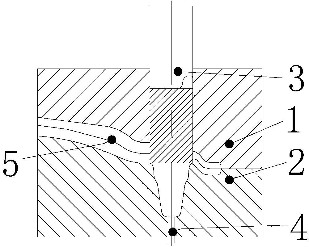
[0032] (A) Making a semi-closed extrusion billet mold: a semi-closed extrusion billet mold consists of four parts: upper die 1, lower die 2, upper punch 3, and ejector rod 4. The upper mold 1 and the lower mold 2 are bonded together to form a cavity 5 matching the contour of the steering knuckle with a support shaft, so as to ensure that the pre-forged workpiece is basically consistent with the terminal molded workpiece. The mold cavity 5 is composed of a supporting shaft cavity 51 and branch cavities 52 with different lengths extending laterally on the upper part of the supporting shaft cavity 51 and mutually independent. The supporting shaft cavity 51 is located in the lower mold 2, and each branch cavity 52 is fitted The thicknes...


PUM


Abstract

The invention discloses a semi-closed type extrusion forging process with a supporting shaft knuckle. The semi-closed type extrusion forging process includes the steps of firstly, manufacturing a semi-closed type extrusion blank manufacturing die, wherein the semi-closed type extrusion blank manufacturing die comprises an upper die body (1), a lower die body (2), an upper punch pin (3) and a material ejecting rod (4), the upper die body and the lower die body are attached together to form a cavity (5) which is matched with the supporting shaft knuckle in the aspect of outline, the cavity comprises a supporting shaft cavity body (51) and branch cavity bodies (52), the branch cavity bodies (52) have different lateral extension lengths at the upper portion of the supporting shaft cavity body and are independent of one another, the supporting shaft cavity body is located in the lower die body, the thicknesses of the portions, on the upper side and the lower side of the attaching face, of each branch cavity body are the same, the branch cavity body with the largest outward extension length is of an open type structure, and the rest of the branch cavity bodies are of a closed type structure; secondly, conducting heating; thirdly, manufacturing a blank through extrusion in a semi-closed mode; fourthly, conducting finish forging and forming; fifthly, cutting edges. The semi-closed type extrusion forging process has the advantages of being less in process steps, good in blank mechanical performance, high in material utilization rate, capable of lowering the number of devices and tonnage of a finish forging device, low in manufacturing cost and the like.

Description

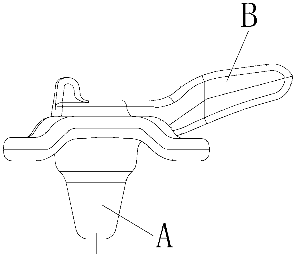
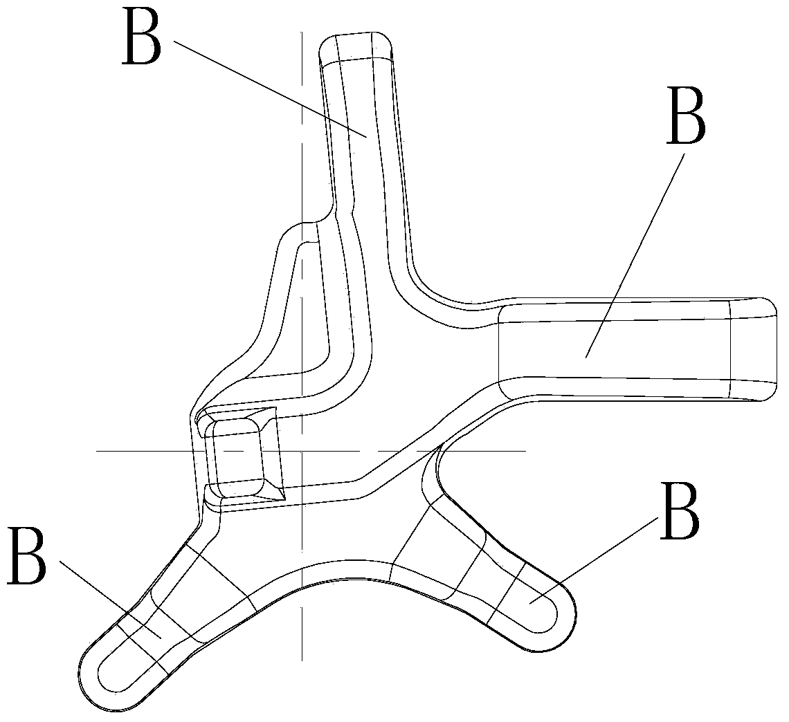
technical field [0001] The invention relates to a forging forming process in the technical field of material processing, in particular to a semi-closed extrusion forging process with a support shaft steering knuckle. Background technique [0002] Such as figure 1 , figure 2 The shown steering knuckle with a support shaft is composed of a support shaft A and a number of branches B extending laterally on the upper part of the support shaft A with different lengths and independent of each other. Among them, one branch B is more B is longer. [0003] The traditional forging process steps of steering knuckle with support shaft are: the traditional process method is: blanking → heating → upsetting support shaft → upsetting and extrusion billet (also called pre-forming) → pre-forging → final forging forming → trimming, a total of 7 procedures. The main problems of traditional crafts are: [0004] (1) There are many process steps, correspondingly, the number of input equipment...

Claims


Application Information

Patent Timeline
IPC IPC(8): B21J5/06B21J1/06B21J13/02
Inventor 周亚夫
Owner CHONGQING YINGGUO MACHINERY MFG
Learn More