
Pointing device with solid-state roller

a technology of solid-state rollers and pointing devices, which is applied in the direction of instruments, computing, electric digital data processing, etc., can solve the problems of mechanical failure and difficult integration into some form factors such as a very low-profile mouse, and achieve the effect of improving features

Inactive Publication Date: 2007-01-30
LOGITECH EURO SA
View PDF22 Cites 54 Cited by
  • Summary
  • Abstract
  • Description
  • Claims
  • Application Information

AI Technical Summary

Benefits of technology

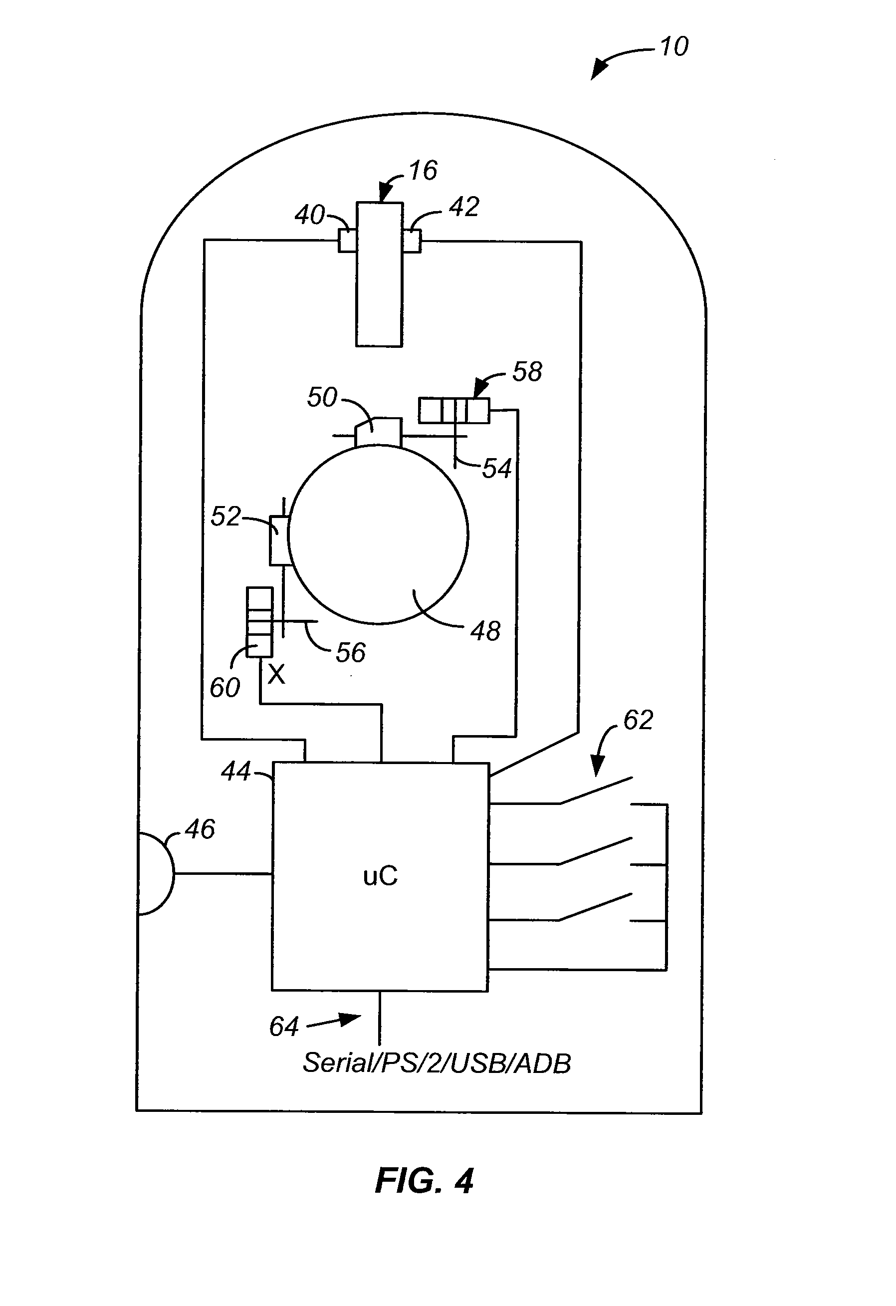
[0007]The present invention provides a solid-state roller on a pointing device with enhanced features. In one embodiment, a capacitive sensor is provided which uses galvanic finger contact. In particular, the finger on an electrode acts as a switch to connect ground, through the body, the body capacitance and a capacitance connected to the electrode. As the finger passes from one electrode to another, movement and direction is sensed. A unique differential detection circuit is also provided, which alternately clamps a node high and then low, allowing measurement of both capacitive charge-up and discharge, to compensate for interference.
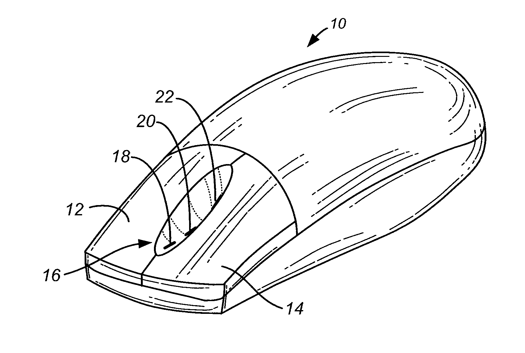
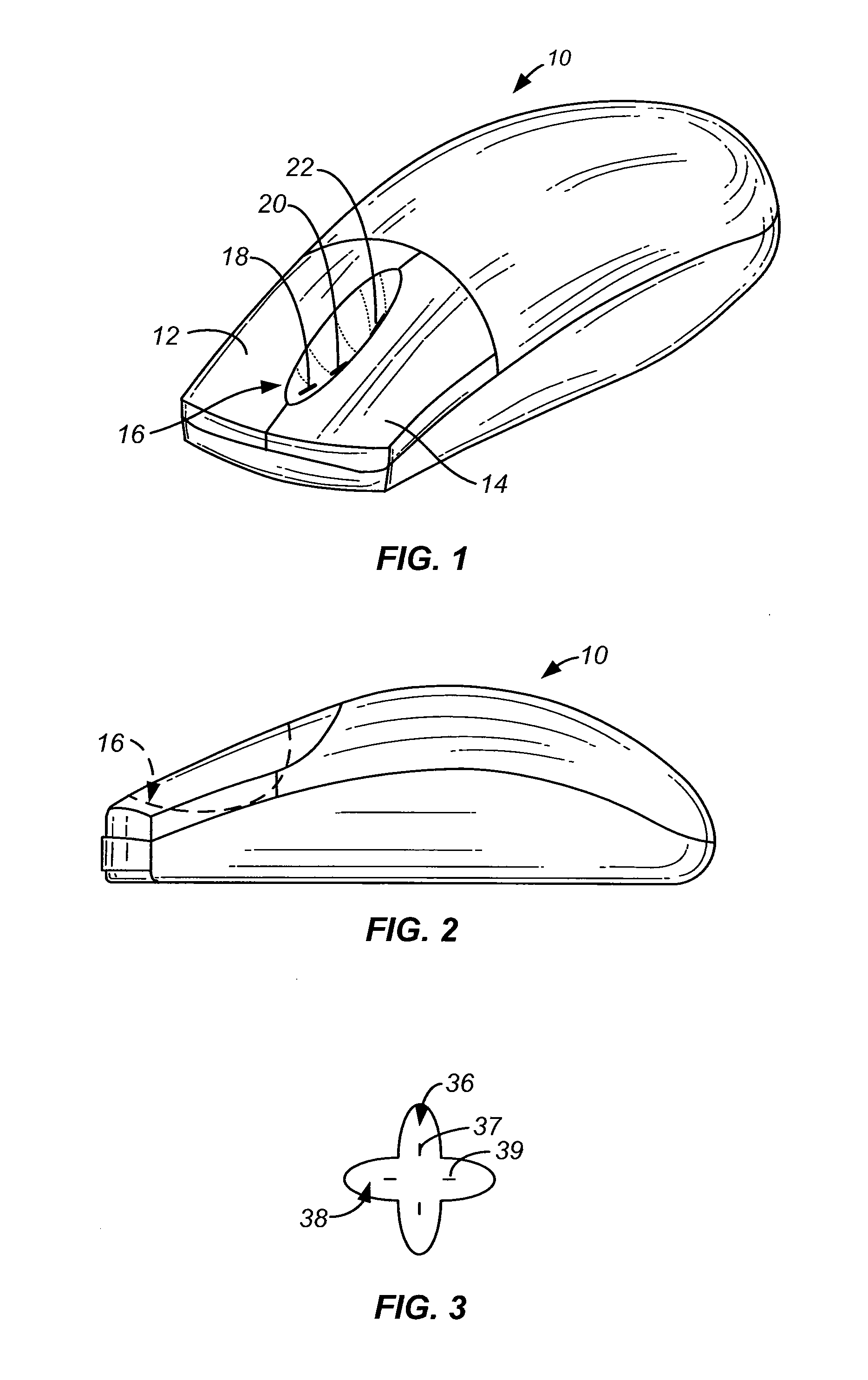
[0008]The solid-state sensor allows multiple shapes to be used. Unlike a touchpad, which is practical to bend in only one direction, the solid-state roller can be on a surface with curvature in more than one direction. It can also be on either a concave or convex surface. In one embodiment, a convex trench or downward curve contains sensors for detecting finger movement. The user's finger can thus bend about a knuckle in a curved motion to activate the sensor, requiring little or no movement of the finger up and down. In another embodiment, the sensor is on a convex surface, such as on a side for activation by the thumb.
[0011]In one embodiment, the speed of finger movement is determined in the pointing device, rather than in a software driver as in the prior art. The signal sent to the computer multiplies the number of transitions in accordance with the detected speed. This allows a single transition to speed up scrolling, rather than requiring multiple reports to a software driver.
[0012]Instead of the mechanical ratchet feedback of the prior art mechanical rollers, the present invention uses other forms of feedback. For example, a clicking sound emanates from a speaker mounted in the pointing device. By using a speaker in the pointing device, instead of the computer speaker, the latency is greatly improved, giving a realistic feedback. Alternately, lights could flash in the mouse. In one embodiment, a light used in the pointing device for decorative purposes can be flashed to indicate a notification to the user. One example would be an event being monitored by the user externally to the computer system, such as over the Internet, with the flashing light in the pointing device prompting the user.

Problems solved by technology

Some of the disadvantages of a roller are that it is a mechanical element, and thus subject to mechanical failure since it is susceptible to dirt and shock.
In addition, its size can make it difficult to integrate into some form factors such as a very low profile mouse.

Method used


Image

  • Pointing device with solid-state roller
  • Pointing device with solid-state roller
  • Pointing device with solid-state roller

Examples


Embodiment Construction

[0036]Curved Solid-state Roller

[0037]The solid-state roller of the invention allows the roller to be placed on any shape housing. A trench or other convex shape could be used. Alternately, a concave shape could be used. A concave shape could be used for placement of the sensor on the side of a mouse, for activation by a thumb. The solid-state design described herein allows the sensor to be placed on any shape of surface, such as one that has curvature in two directions. Thus, it could simply track the contour of the mouse or other pointing device. This allows a pointing device to be designed for aesthetic or ergonomic reasons, and a solid-state roller can be added without requiring the shape to change.

[0038]Various shape implementation are covered in the invention. A curved trench with curvature matched to the hand creates a support surface that is lower than that of the two neighboring surfaces. This reduces the strain on the scrolling finger. Alternatively, the three middle finger...


PUM


Abstract

A solid-state roller on a pointing device with enhanced features. The solid-state design described herein allows the sensor to be placed on any shape of surface, such as one that has curvature in two directions. In one embodiment, a trench or downward curve contains sensors for detecting finger movement. The user's finger can thus bend about a knuckle in a curved motion to activate the sensor, requiring little or no movement of the finger up and down. The solid-state sensors can be of one of a number of designs. In one embodiment, multiple electrodes are contacted by a finger as it moves. Each electrode is coupled to a capacitive detection circuit, for detecting the change in capacitance as the electrode is contacted by the finger.

Description

CROSS-REFERENCE TO RELATED APPLICATIONS[0001]This application claims priority from U.S. Provisional Application No. 60 / 258,133, filed Dec. 22, 2000, which application is incorporated herein by reference.BACKGROUND OF THE INVENTION[0002]The present invention relates to a solid-state roller (with no moving parts) on a pointing device, such as a computer mouse.[0003]A number of computer mice include a roller or wheel which can be rotated by a user's finger. Typically, such a roller is used for scrolling. One example is set forth in Logitech U.S. Pat. No. 6,157,369, and other examples are described in the background section of that patent. Some of the disadvantages of a roller are that it is a mechanical element, and thus subject to mechanical failure since it is susceptible to dirt and shock. In addition, its size can make it difficult to integrate into some form factors such as a very low profile mouse.[0004]Other patents describing a roller or wheel include U.S. Pat. Nos. 5,530,455 a...

Claims


Application Information

Patent Timeline
IPC IPC(8): G09G5/08G09G5/00
CPCG06F3/03543G06F3/033G06F3/0362
Inventor KEHLSTADT, FLORIAN MAXJOSS, BERNIPIOT, JULIENBIDIVILLE, MARCPLANCHEREL, LAURENTMERMINOD, BAPTISTEDUPRAZ, JEAN-LUCMARINI, MAXIMEYU, CHIU
Owner LOGITECH EURO SA
Learn More