Hinge for extended grabber tool

a technology of extended grabber and hinge, which is applied in the direction of hinges, manufacturing tools, hoisting equipment, etc., can solve the problems of increasing the complexity of a proposed device, increasing the cost of parts, and increasing the cost of manufacturing and parts, so as to reduce the strength of the rod. , the effect of convenient storag

Inactive Publication Date: 2005-02-01
ONTEL PRODS
View PDF8 Cites 58 Cited by
  • Summary
  • Abstract
  • Description
  • Claims
  • Application Information

AI Technical Summary

Benefits of technology

The device also incorporates a hinge feature on the elongate rod that enables the elongate arm to be folded in half so that the device may be shipped and stored conveniently. The hinge, which is provided at a midpoint along the elongate rod, does not significantly diminish the strength of the rod. The hinge uses a pin that has axial sections that alternate from sections having a circular profile to sections having an aster

Problems solved by technology

While, there exist numerous types of devices and a variety of alternative manners in which to lock engagement elements in fixed positions, many of the efforts disclosed in the prior art have involved fairly complex arrangements and require multiple parts.
In general, increased complexity of a prop

Method used


Image

  • Hinge for extended grabber tool
  • Hinge for extended grabber tool
  • Hinge for extended grabber tool

Examples


Embodiment Construction

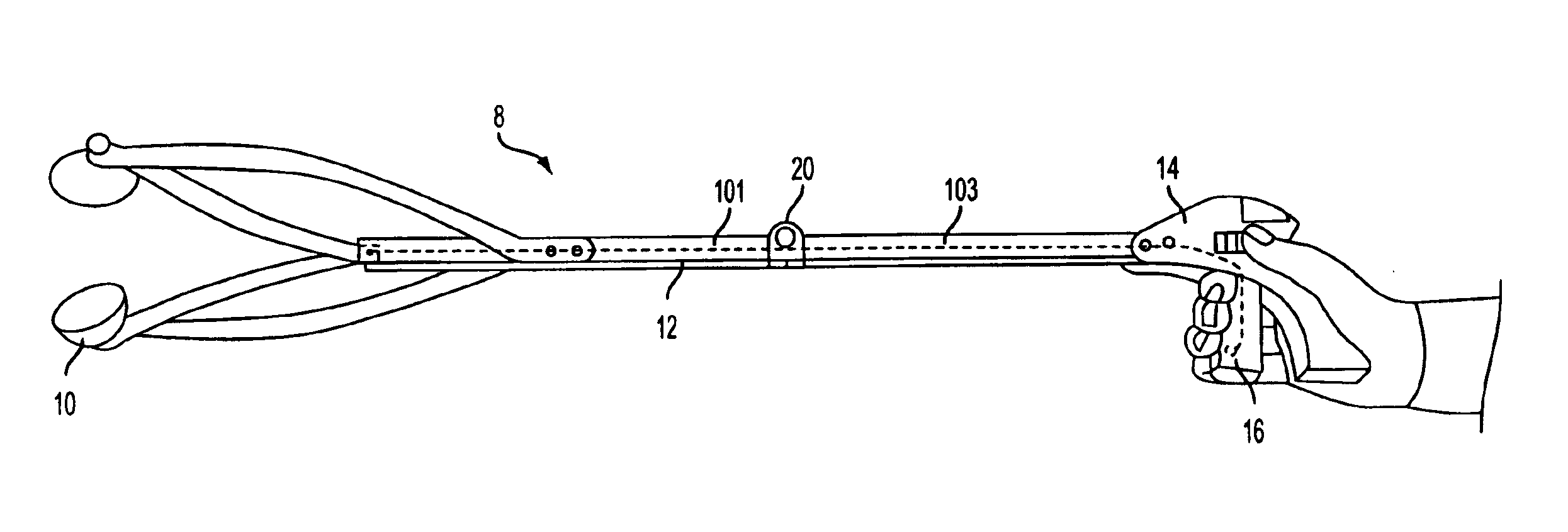
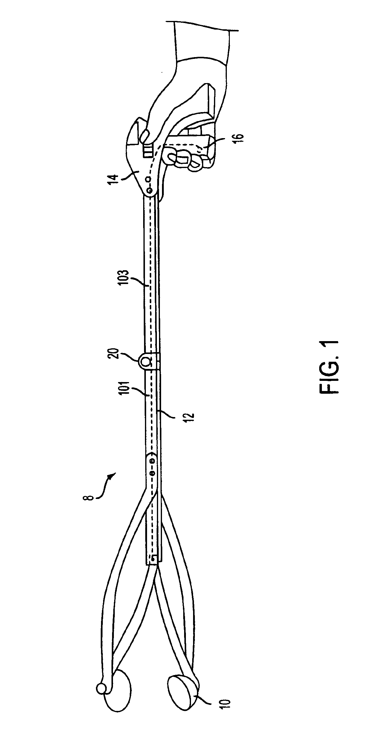
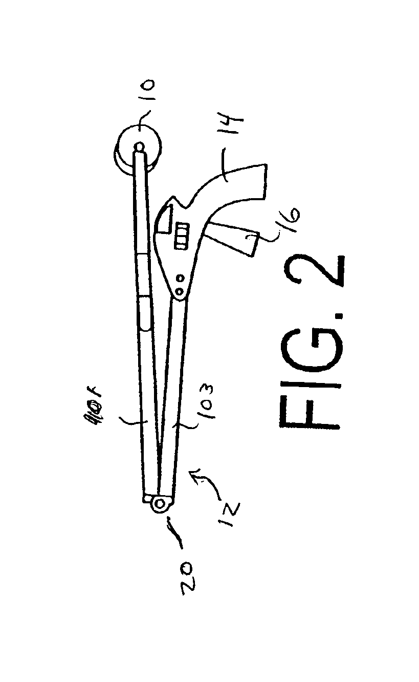
Now referring to FIG. 1, a preferred embodiment of the elongate grabber tool 8 is depicted in an extended position. Grabber tool 8 incorporates engagement cups 10 on a distal end of a elongate hollow rod 12 and a pistol grip 14 on the opposite proximal end. A trigger 16 is provided adjacent to pistol grip 14 for manipulation by a user's fingers. As shown on the side of pistol grip 14, a switch 18 is provided that effects a locking feature of the engagement elements of the device. At a medial point on elongate hollow rod 12 is hinge 20 that allows elongate rod 12 to fold. FIG. 2 depicts the rod in a folded position wherein the distal end of elongate rod 12 is folded back on the top side and adjacent to pistol grip 14.

Now referring to FIG. 3, trigger 16 extends from and is connected to the handle at axis or pivot point 30 that is located near the top of the pistol grip 14. A connecting pin 32 transects handle side 25a, the trigger half 16a, trigger half 16b and handle side 25b. Trigge...


PUM


Abstract

An elongate engagement tool that has engagement elements located on a distal end of a first rod, a handle on the proximate end of second rod, a controller on the handle to control the engagement elements, and a linkage between the controller and engagement elements to control the engagement elements is disclosed. The rods are connected together by a locking hinge. A locking pin is received by the knuckles of the hinges has a plurality of axial segments. The profiles of the axial segments alternate from round disks to aster shaped disks that closely fit into the apertures formed by the knuckles. When the locking pin is moved to a first locked position where the aster shaped profiled sections are aligned with the apertures in the corresponding knuckles to the hinge is locked. Movement of the pin to a second free position where the round axial sections are aligned with the apertures in the knuckles provides for limited rotational movement.

Description

BACKGROUND OF THE INVENTIONThere are a wide variety of tools designed for picking up objects or manipulating objects from a distance. One common application for such tools is use by maintenance workers to pick-up debris for subsequent disposal. A tool with an elongate handle allows manipulation of the object without the need to bend over or to directly handle the material. Such tools are also useful for individuals that have physical handicaps that may impede their ability to bend over and reach the ground. There are also numerous household applications for such tools including retrieval of materials from high shelves or from under furniture. Another common application for such tools is for changing light bulbs from recessed lighting fixtures. Another entire class of devices that operate in a similar manner and perform a similar function as the pick-up tools described above are marketed as toys. Other tools may have blades on the distal end for cutting that may be used for a wide ra...

Claims


Application Information

Patent Timeline
IPC IPC(8): B25G1/00B25G1/06B25J21/02B25J21/00
CPCB25G1/06B25J21/02Y10T16/540253
Inventor KHUBANI, ASHOKLAKHIANI, MAHESH
Owner ONTEL PRODS
Why Eureka
Try Eureka