
Cutting tool with two cutting inserts in a single flute

A cutting insert and cutting tool technology, which is applied to tools for lathes, accessories of toolholders, turning equipment, etc., can solve the problems of complex cutting insert structure, poor chip breaking and chip tolerance, and difficulty in precision control. Simple structure, improving cutting efficiency and reducing cost of use

Active Publication Date: 2016-02-17
ZHUZHOU CEMENTED CARBIDE CUTTING TOOLS CO LTD
View PDF12 Cites 0 Cited by
  • Summary
  • Abstract
  • Description
  • Claims
  • Application Information

AI Technical Summary

Problems solved by technology

[0002] In order to increase the number of effective edges that the cutting tool participates in cutting, people put the cutting blade with a double-layer cutting edge structure into the sipe of the cutting tool, so that the cutting blade in a single sipe can be cut twice successively to increase the number of cutting blades involved in cutting. However, in order to ensure the strength of the cutting edge that first participates in cutting in the cutting insert with double-layer cutting edge structure, the groove space corresponding to the cutting edge that participates in cutting later is very small, and the general design is very simple. The ability is very poor, so this kind of cutting tool equipped with cutting inserts with double-layer cutting edges can only be used in occasions where the cutting force is not large and brittle materials are processed, and one of the two-layer cutting edges must be replaced after one layer of cutting edge is worn out. The entire blade has a high cost of use. At the same time, the cutting blade with double-layer cutting edges has a complex structure, difficult precision control, and high manufacturing costs.

Method used


Image

  • Cutting tool with two cutting inserts in a single flute
  • Cutting tool with two cutting inserts in a single flute
  • Cutting tool with two cutting inserts in a single flute

Examples


Embodiment Construction

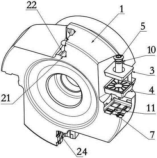
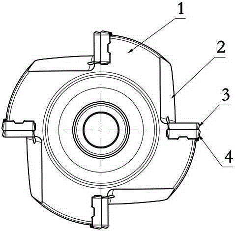
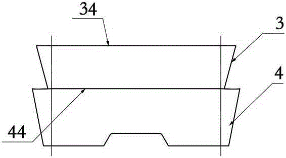
[0035] Figure 1 to Figure 7 It shows the first embodiment of the cutting tool with two cutting blades with a single sipe of the present invention, the cutting tool includes a cutter body 1, at least one set of sipe 2 is arranged on the cutter body 1, and the sipe 2 passes through a tight The firmware 5 is fixed with a cutting blade group consisting of a first cutting blade 3 and a second cutting blade 4, the first cutting blade 3 is pressed on the second cutting blade 4, and the second cutting blade 4 is pressed on the sipe 2 , during cutting, the first cutting blade 3 and the second cutting blade 4 complete the cutting independently successively, and an independent first cutting blade 3 and a second cutting blade 4 are arranged in a single sipe, and the two cutting blades can share a large The groove design space can greatly improve the chip removal performance, thereby improving the cutting efficiency of the cutting tool; at the same time, the damage of the cutting edge of ...


PUM


Abstract

The invention discloses a cutting cutter of which a single cutter groove provided with two cutting blades. The cutting cutter comprises a cutter body which is provided with at least one cutter groove group. A cutting blade group composed of the first cutting blade and the second cutting blade is fixed in the cutter groove through fasteners. The first cutting blade is pressed on the second cutting blade and the second cutting blade is pressed on the cutter groove. In the time of cutting, the first cutting blade and the second cutting blade perform cutting independently in sequence. The cutting cutter of which the single cutter groove provided with the two cutting blades has the advantages of being simple in structure, convenient to manufacture, smooth in chip discharging, high in cutting efficiency and capable of saving cost.

Description

technical field [0001] The invention relates to the field of metal cutting, in particular to a cutting tool with two cutting blades in a single groove. Background technique [0002] In order to increase the number of effective edges that the cutting tool participates in cutting, people put the cutting blade with a double-layer cutting edge structure into the sipe of the cutting tool, so that the cutting blade in a single sipe can be cut twice successively to increase the number of cutting blades involved in cutting. However, in order to ensure the strength of the cutting edge that first participates in cutting in the cutting insert with double-layer cutting edge structure, the groove space corresponding to the cutting edge that participates in cutting later is very small, and the general design is very simple. The ability is very poor, so this kind of cutting tool equipped with cutting inserts with double-layer cutting edges can only be used in occasions where the cutting fo...

Claims


Application Information

Patent Timeline
Patent Type & Authority Patents(China)
IPC IPC(8): B23D79/00B23B27/00
Inventor 江爱胜王社权汤爱民
Owner ZHUZHOU CEMENTED CARBIDE CUTTING TOOLS CO LTD
Learn More