Application method of clamp with abrasive flow wiping stainless steel tubes

A stainless steel tube and abrasive flow technology, which is applied in the direction of grinding machines, manufacturing tools, grinding workpiece supports, etc., can solve the problems that stainless steel tubes are easily deformed and cannot be fixed firmly at the same time, so as to improve the wiping effect, improve the wiping efficiency, insert and fix The effect of easy operation

Inactive Publication Date: 2014-04-09
郝鹏飞
View PDF6 Cites 8 Cited by
  • Summary
  • Abstract
  • Description
  • Claims
  • Application Information

AI Technical Summary

Problems solved by technology

[0003] The purpose of the present invention is to overcome the above shortcomings, improve the wiping efficiency, improve the wiping effect, and solve the problems in the above technology that multiple stainless steel pipes of equal length cannot be firmly fixed at the sa

Method used


Image

  • Application method of clamp with abrasive flow wiping stainless steel tubes
  • Application method of clamp with abrasive flow wiping stainless steel tubes
  • Application method of clamp with abrasive flow wiping stainless steel tubes

Examples


Embodiment 1

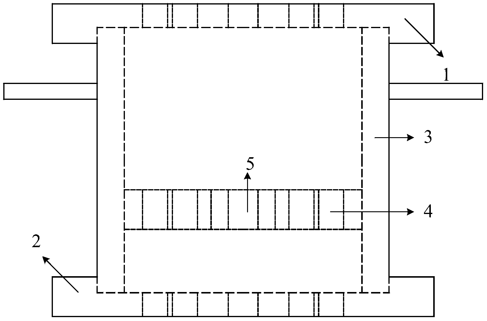
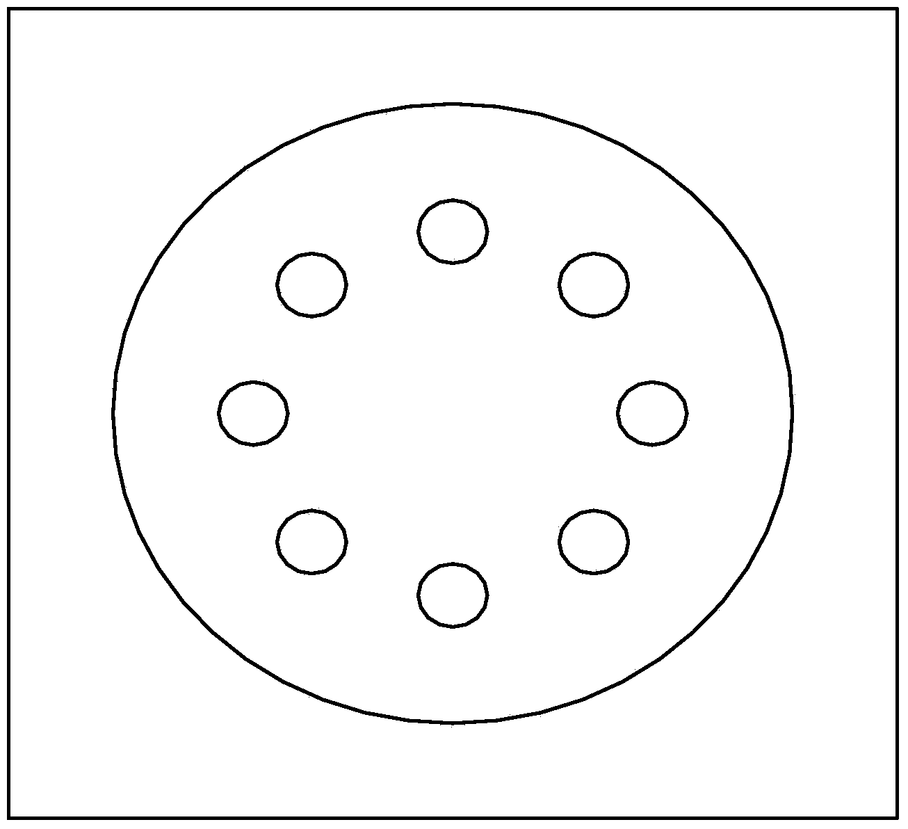
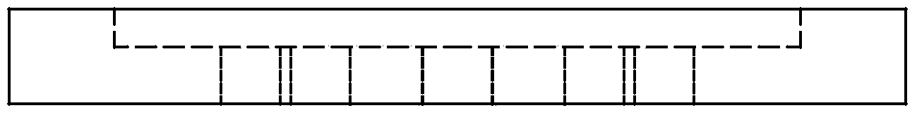
[0030] like figure 1 — Figure 6 As shown, this embodiment includes an upper retaining guide plate 1, a lower retaining guide plate 2, a bearing sleeve 3 and a limit sleeve 4, the lower surface of the upper retaining guide plate 1 is closely combined with the upper end of the bearing sleeve 3, and the lower retaining guide plate The upper surface of the plate 2 is closely combined with the lower end of the bearing sleeve 3, the limit sleeve 4 is tightly arranged in the load sleeve 3, the limit sleeve 4 is parallel to the upper guide plate 1 and the lower guide plate 2, and the upper guide plate Correspondingly, there are 8 sockets 5 whose diameter is the outer diameter of the stainless steel pipe on the plate 1, the lower retaining guide plate 2 and the limit sleeve 4. On the lower surface of the upper baffle guide plate 1, the center of the upper baffle guide plate 1 is the center of the circle and has a circular concave platform draw-in groove with a diameter of the outer d...

Embodiment 2

[0037] In this embodiment, there are 16 sockets 5 whose diameter is the outer diameter of the stainless steel pipe correspondingly on the upper retaining guide plate 1, the lower retaining guide plate 2 and the limit sleeve 4, and the rest of the structures are the same as in the embodiment 1.

Embodiment 3

[0039] In this embodiment, 28 sockets 5 whose diameter is the outer diameter of the stainless steel pipe are correspondingly provided on the upper retaining guide plate 1, the lower retaining guide plate 2 and the limit sleeve 4, and the rest of the structures are the same as in the embodiment 1.


PUM


Abstract

The invention discloses an application method of a clamp with abrasive flow wiping stainless steel tubes. The application method includes the following steps that firstly, a plurality of stainless steel tubes with the same length are inserted into stop collars along insertion holes of the stop collars to form a stop collar set; secondly, the lower ends of the stainless steel tubes of the stop collar set are inserted into insertion holes of a lower blocking and guiding board; thirdly, a bearing sleeve is clamped in a concaved table clamping groove of the lower blocking and guiding board; fourthly, the insertion holes of an upper blocking and guiding board align with the upper ends of the stainless steel tubes of the stop collar set, the upper ends of the stainless steel tubes are inserted into the insertion holes, and then the concaved table clamping groove of the upper blocking and guiding board tightly clamps the upper end of the bearing sleeve; fifthly, the clamp and the stainless steel tubes which are tightly clamped and integrally fixed are placed between a feeding cylinder and a discharging cylinder of an abrasive flow machine tool, the machine tool is started, and then abrasive flow wiping can be performed on the inner walls of the stainless steel tubes in the clamp. According to the application method, the pressure for bearing the abrasive flow machine tool can be scattered, the stainless steel tubes are protected against deformation when being subjected to pressure in the wiping process, multiple stainless steel tubes can be fixed and wiped at the same time, and therefore the wiping efficiency and the wiping effect are improved.

Description

technical field [0001] The invention belongs to the technical field of mechanical engineering and pipeline cleaning, and in particular relates to a method for using an abrasive flow wiping fixture for a plurality of equal-length stainless steel tubes. Background technique [0002] As an important carrier for long-distance transportation of oil and gas, stainless steel pipes are playing an increasingly prominent role in modern industrial construction. Especially in the field of aerospace, there is a high requirement for the purity of the gas and liquid to be transported, so there is a high requirement for the cleanliness of the inner wall of the transport pipeline. At present, the cleaning and wiping of the inner wall of the stainless steel pipe is still mostly solved by using a push-pull cleaner, which has low wiping efficiency and is difficult to guarantee the wiping effect. However, there is no systematic product for the new abrasive flow wiping technology for the inner w...

Claims


Application Information

Patent Timeline
IPC IPC(8): B24B41/06B24B27/033
CPCB24B41/06
Inventor 郝鹏飞侯晓波高家智刘卫东张平史建虎侯华司文姬
Owner 郝鹏飞
Why Eureka
Try Eureka