
Step of automatic escalator

A step and elevator technology, applied in escalators, transportation and packaging, etc., can solve the problems of fatigue damage, spending a lot of time and cost, easy to attach dirt and dirt, etc., and achieve the effect of preventing serious injuries

Active Publication Date: 2014-04-09
TOSHIBA ELEVATOR KK
View PDF6 Cites 1 Cited by
  • Summary
  • Abstract
  • Description
  • Claims
  • Application Information

AI Technical Summary

Problems solved by technology

These mechanisms are required for each step, so there is a problem that the cost of the escalator as a whole is very high
In addition, when the mechanism does not work, it is very likely to cause damage to the comb teeth of the entrance and exit part, thereby damaging all the steps
In addition, the comb teeth are subjected to force and rubbed every time they pass through the steps, so there are concerns about fatigue damage and wear
As such, there are problems of high cost and low reliability in this method
[0007] In addition, in the method proposed in Patent Document 2, since the comb plate is made of rubber or synthetic resin, there is a problem that it is easier to wear than the conventional comb plate, and it is easy to adhere to dirt and dirt, and its life is short.
In addition, when replacing the comb plate that has reached the end of its life, there is a problem that the entire tread must be replaced, and the replacement takes a lot of time and money.
In addition, when the comb plate is made of rubber, if the weight of the passenger acts on the comb plate to deform, the pedals will become unstable, which may cause the passenger to fall.
[0008] In addition, the method proposed in Patent Document 3 has the problem of not taking countermeasures for the corners of the most dangerous steps from the viewpoint of preventing serious injuries, since the original purpose of the proposal is to prevent vibration transmission.
The elastic vibration suppression material placed between the steps and the frame is not sufficient to absorb the impact energy, so there is also a problem that it is ineffective in preventing serious injuries
In addition, since the elastic damping material is laid on most of the base of the tread, there is a problem of increased material costs, assembly costs, and high costs.

Method used


Image

  • Step of automatic escalator
  • Step of automatic escalator
  • Step of automatic escalator

Examples


Embodiment 1

[0049] currently in use Figure 1 to Figure 9 The structure of Embodiment 1 will be described.

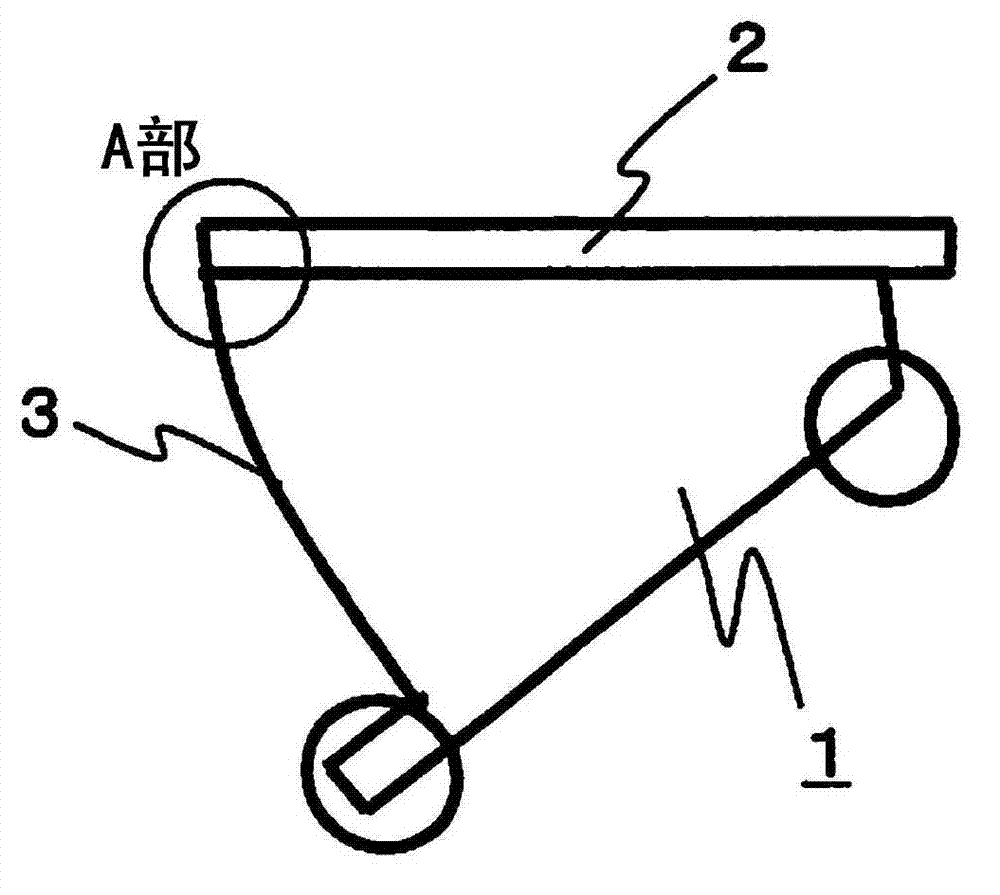
[0050] figure 1 It is a side view of step 1 of the escalator. The upper part of the step 1 has a tread 2 on which passengers ride, ascending or descending. In the description below, the figure 1 The direction of travel when rung 1 ascends ( figure 1 The middle is the right side) is defined as the front side, its opposite direction ( figure 1 The left side in the middle) is defined as the rear side for illustration. A step riser portion 3 is provided at the rear end of the step 1, and a corner portion (part A in the figure) is formed by intersecting the rear end of the tread 2 at its upper portion.

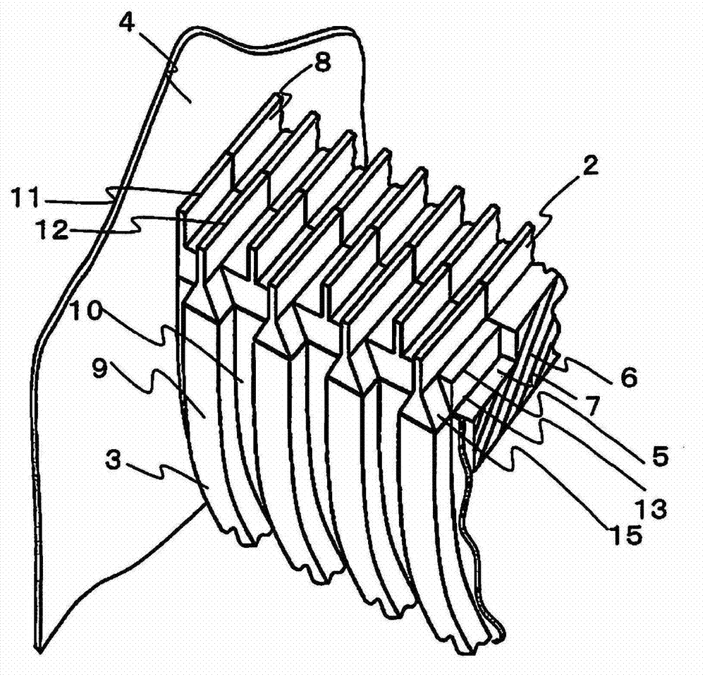
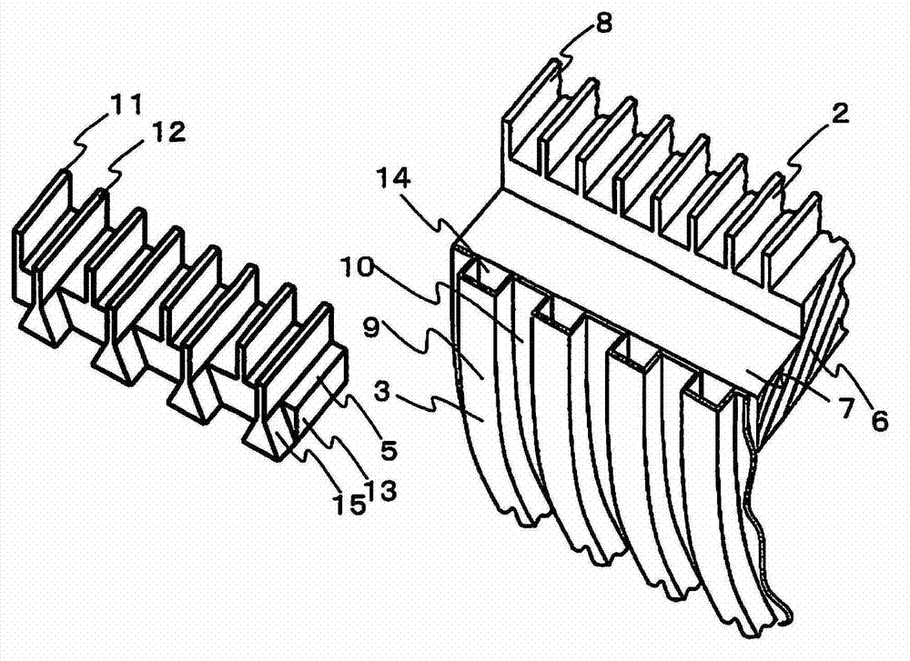
[0051] figure 2 and image 3 It means that the corner is seen from the center of the step 1 along the step baffle 4 ( figure 1 A partial perspective view of the state of Part A). figure 2 It shows the state after attaching the impact-absorbing splint 5 to the main body porti...

Embodiment 2

[0075] currently in use Figure 10 to Figure 12 Embodiment 2 will be described.

[0076] The difference between Embodiment 2 and Embodiment 1 is that the materials of each part constituting the impact-absorbing splint 20 are different, and their shapes are the same. Therefore, different parts will be described below, and descriptions of other parts will be omitted.

[0077] The impact-absorbing splint 20 of Example 2 also uses two kinds of urethane rubbers, urethane rubber with relatively high hardness and urethane rubber with relatively low hardness.

[0078] Figure 10 is the cross-section of the base 23 representing the short peak 21 and its lower portion ( Figure 5 A-A section in). The short peak 21 and the base 23 use relatively hard materials.

[0079] Figure 11 is to represent the base 23 section of the long peak 22 and its lower part ( Figure 5 B-B section in). Changfeng 22 using hardness compared to Figure 10 The shown short peak 21 and its lower base 23 ...

Embodiment 3

[0090] currently in use Figure 13 to Figure 15 Embodiment 3 will be described.

[0091] The difference between Embodiment 3 and Embodiment 1 is that, as in Embodiment 2, the materials of each part constituting the impact-absorbing splint 30 are different, and their shapes are completely the same. Therefore, different parts will be described below, and descriptions of other parts will be omitted.

[0092] The impact-absorbing splint 30 of Example 3 also uses two kinds of urethane rubbers, urethane rubber with relatively high hardness and urethane rubber with relatively low hardness.

[0093] Figure 13 is the cross-section of the base 33 representing the short peak 31 and its lower portion ( Figure 5 A-A section in). A relatively hard material is used for the short peak 31 and the base 33 .

[0094] Figure 14 is to represent the base 33 section of the long peak 32 and its lower part ( Figure 5 B-B section in). A material with relatively low hardness is used for the ...


PUM


Abstract

The invention provides a step of an automatic escalator, wherein a corner part of a crossed part between a tread surface and a tread vertical plate part is provided with a clamping plate used for absorbing impact. The tread surface main body adopts the aluminum or the stainless steel and other metal materials. The clamping plate adopts the elastomer containing the natural rubber, the synthetic rubber, the polyurethane rubber, the silicone rubber, and the fluororubber. According to the step, the clamping plate adopts more than two elastomers. By adopting the invention, the safe automatic escalator can be provided, and without using the high-price device, the head of the passenger can be protected from being injured severely, even when the head is collided with the corner of the step. And in addition, the passenger cannot easy fall down even during the common utilization state.

Description

technical field [0001] The invention relates to a step of an automatic elevator. Background technique [0002] Overturning accidents often occur in automatic elevators, especially when the body collides with the corner where the tread of the step and the riser face intersect (hereinafter referred to as "the corner of the step"), there is a possibility of serious injury. Therefore, there is a need for a safe automatic elevator that can absorb the collision energy even if the head hits the corners of the steps when it falls down, so as to prevent serious injuries. However, it is not a structure that encourages the passenger to fall in a normal use state even if the injury is prevented from becoming serious when the vehicle falls over. [0003] Conventionally, several methods have been proposed as measures to prevent serious injuries when the body collides with the step corner. For example, Japanese Patent Laying-Open No. 2008-254873 (Patent Document 1) proposes such an autom...

Claims


Application Information

Patent Timeline
IPC IPC(8): B66B23/12
Inventor 中垣熏雄上村晃正石川佳延菊地孝幸高桥秀生
Owner TOSHIBA ELEVATOR KK
Learn More