Borehole imaging device

A technology of borehole imaging and host computer, which is applied in the directions of earthwork drilling, measurement, wellbore/well components, etc., can solve the problem of not being able to obtain the plane development map and 3D histogram of the fissures of the borehole wall, the position of the section line is not the same, Error and other problems, to improve the installation and test video image data acquisition conditions, high definition, high integration effect

Active Publication Date: 2014-04-09
SICHUAN UNIV
View PDF6 Cites 43 Cited by
  • Summary
  • Abstract
  • Description
  • Claims
  • Application Information

AI Technical Summary

Problems solved by technology

[0006] ①The probe of the borehole imager will rotate during the process of pushing into the borehole, which will cause the position of the section line to be different when each frame of image is unfolded into a plan view during the post-processing of video image data. Therefore, the plane view of each frame is Dislocation will occur when the expansion diagrams are pieced together, and a continuous and complete planar expansion diagram and three-dimensional histogram of the borehole wall cracks cannot be obtained
[0007] ②The azimuth and inclination of the borehole are fixed values ​​determined manually before drilling, but the borehole is not an absolute straight line, and its azimuth and inclination do not remain the same. Bending occurs due to the influence of various factors, and there must be a certain deviation between the azimuth and inclination of the drilling hole and the preset value during drilling
This problem directly leads to a large error between the actual azimuth and inclination of the borehole and the value used in the calculation, and ultimately leads to a large error in the measured occurrence of the borehole fracture space

Method used


Image

  • Borehole imaging device
  • Borehole imaging device
  • Borehole imaging device

Examples


Embodiment

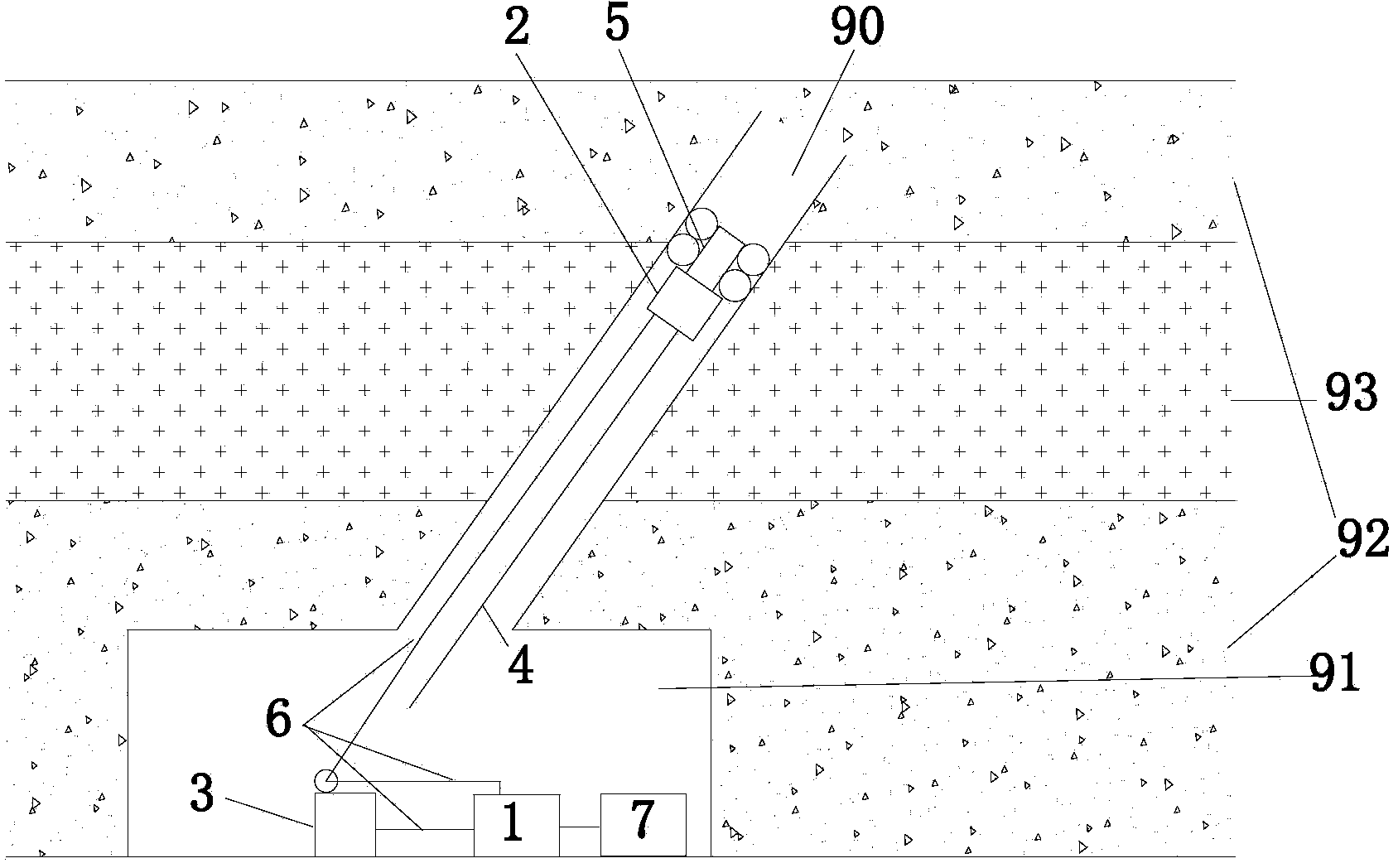
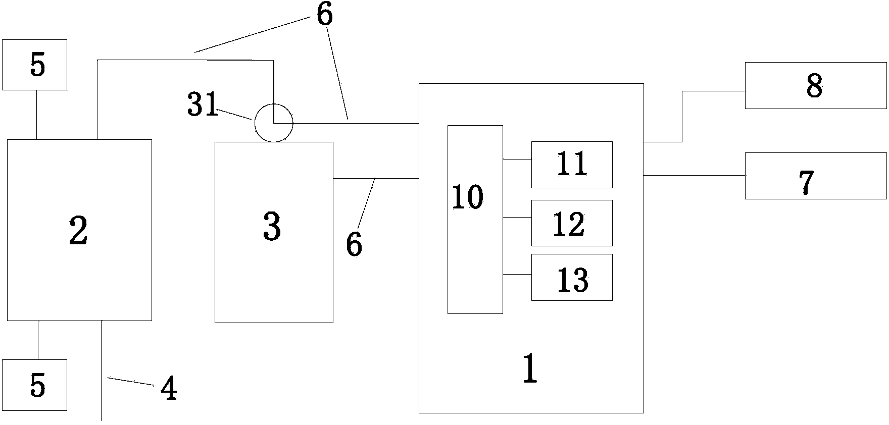
[0067] In this example, the main body 1 of the borehole imager is in the shape of a cuboid, with a length of 288mm, a width of 223mm, a height of 95mm, and a weight of about 3kg. Powered by hydrogen battery, continuous working time is more than 8 hours. The dimming control module 11 of the borehole imager host 1 is used to adjust the brightness of the borehole imager probe 2 to the most appropriate brightness, so as to improve the imaging clarity. In order to enable the nickel-metal hydride battery to be used repeatedly, save costs, and be environmentally friendly, the device in this example further includes a charger 8, which is connected to the nickel-metal hydride battery of the borehole imager host 1 and has a rated working voltage of 220V.

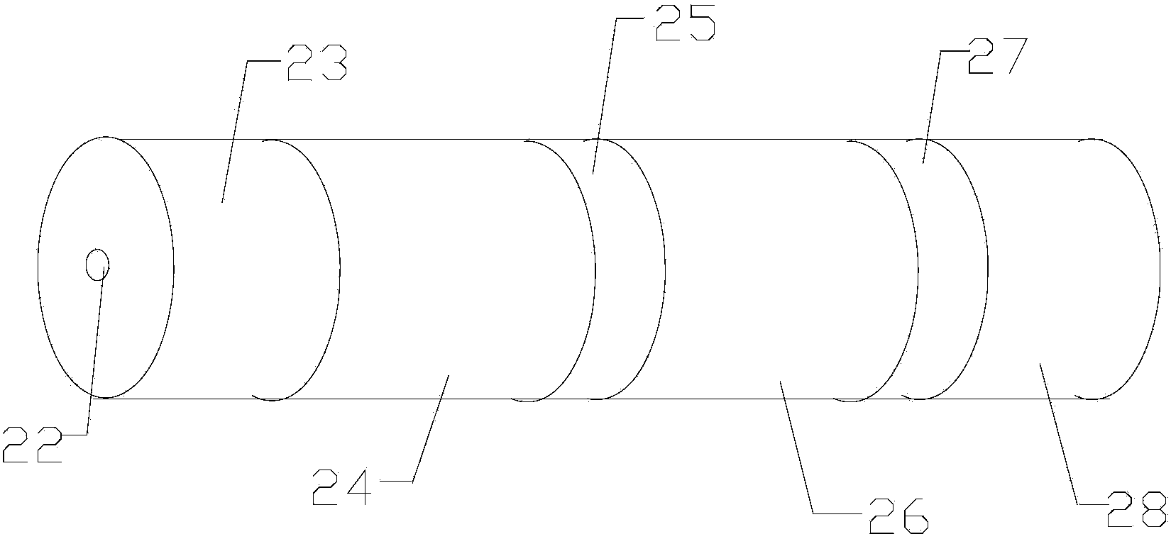
[0068] The borehole imager probe 2 is cylindrical, with a bottom diameter of 24mm, a height of 303mm, and a weight of about 1kg. It is powered by the borehole imager host 1 and has a rated working voltage of 12V; a three-dimensional c...


PUM


Abstract

The invention relates to an imaging device and provides a borehole imaging device. According to the borehole imaging device, panoramic photography of a borehole can be achieved with a borehole imager probe of a built-in three-dimensional compass, a continuous and complete plane development and a continuous and a complete three-dimensional histogram of a borehole wall fracture can be obtained, and the accuracy of a measured borehole fracture spatial occurrence can be improved. According to the technical scheme aiming to solve the technical problems, the borehole imaging device comprises a borehole imager body, the borehole imager probe, a depth counter, a probe pushing rod, a centering device and a data processor, the three-dimensional compass is arranged in the borehole imager probe, the borehole imager body is connected with the depth counter and the data processor, the centering device is arranged on the top of the borehole imager probe, the probe pushing rod is arranged on the bottom of the borehole imager probe, and the borehole imager probe is connected with the depth counter. The borehole imaging device can achieve panoramic photography and is suitable for being used for detecting the borehole fracture spatial occurrence.

Description

technical field [0001] The present invention relates to an imaging device, in particular to a borehole imaging device that can detect the occurrence of a fracture space in a borehole. Background technique [0002] With the rapid development of my country's economy and science and technology, the demand for energy, especially coal, oil and natural gas, is also increasing. In the past 10 years, the production and consumption of coal in China has shown a continuous and rapid increase, and it is the largest coal producer and consumer in the world. However, the geological conditions of coal mines in my country are extremely complex, with high in-situ stress, large variation gradient, high gas content and poor gas permeability, serious coal and gas outbursts, and difficult mining. Production problems are prominent. [0003] Gas outburst is closely related to gas flow in coal seam pores or fissures, and the spatial occurrence of coal-rock fissures is very important to study gas fl...

Claims


Application Information

Patent Timeline
Patent Type & Authority Applications(China)
IPC IPC(8): E21B49/00E21B47/002E21B47/022
Inventor 高明忠张茹谢晶谭强帅春高春玉金文城徐晓练李圣伟
Owner SICHUAN UNIV
Why Eureka
Try Eureka