Mold bar push-out mechanism in capsule production system

A technology of capsule production system and ejection mechanism, which is applied to electromechanical devices, mechanical equipment, and mechanical energy control, etc., can solve the problems of high noise, easy wear and tear, and inconvenient maintenance.

Inactive Publication Date: 2014-04-09
DANDONG JINWAN GRP
View PDF7 Cites 7 Cited by
  • Summary
  • Abstract
  • Description
  • Claims
  • Application Information

AI Technical Summary

Problems solved by technology

Due to the need for multiple gears and other transmission components, the structure is complex, installation and debugging are inconvenient, and maintenance is not easy. The noise is loud during operation, and it is easy to wear, which affects the service life.

Method used


Image

  • Mold bar push-out mechanism in capsule production system
  • Mold bar push-out mechanism in capsule production system
  • Mold bar push-out mechanism in capsule production system

Examples


Embodiment

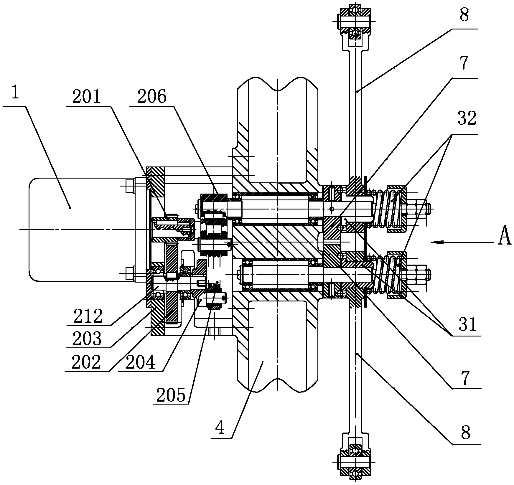
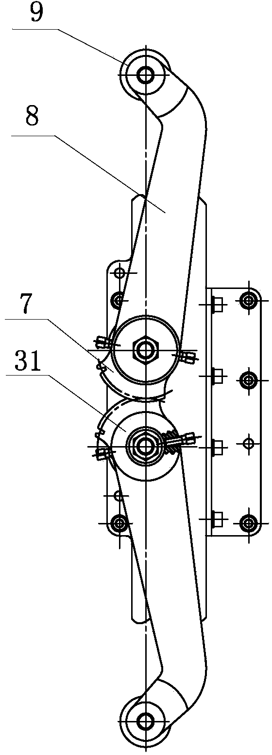
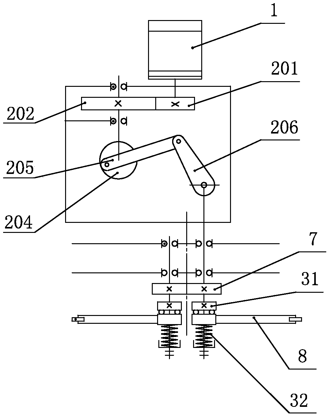
[0026] Example: such as figure 1 , figure 2 As shown, the present invention is installed on the push-out crossbeam 4 of the dipping machine, including a push-out motor 1, a transmission device 2, an active push-out shaft 5, a driven push-out shaft 6, two push-out arms 8 and an overload protection device 3 thereof. The push-out shaft 5 and the driven push-out shaft 6 are all installed on the push-out crossbeam 4, and one end of the active push-out shaft 5 and the driven push-out shaft 6 stretches out the push-out crossbeam 4, and the half teeth 7 which mesh with each other are respectively installed on it, and the two push-out arms 8 respectively Installed on the active push-out shaft 5 and the driven push-out shaft 6, the overload protection device 3 is installed at the ends of the active push-out shaft 5 and the driven push-out shaft 6 where the push-out arm 8 is installed, and the other end of the active push-out shaft 5 protrudes out of the push-out beam 4. Connect the ej...

Embodiment 2

[0034] Embodiment 2: The difference between this embodiment and Embodiment 1 is that the transmission device 2 includes a box body 203 and intermeshed third and fourth gears 208 and 209 placed in the box body 203, an in-situ trigger ring 210 and The trigger ring 211 is in place, the third gear 208 is installed on the ejection motor shaft, the fourth gear 209 is installed on the active ejection shaft 5 extending into the transmission box 203, the fourth gear 209 has a sleeve structure, The active release shaft 5 end at the fourth gear 209 end is equipped with an in-situ trigger ring 210, and the sleeve outer sleeve of the fourth gear 209 is equipped with a trigger ring 211 in place; the active release shaft 5 rotates to the trigger position of the trigger ring in place, and the motor 1 is released. Reverse and return, the active push-out shaft 5 rotates to the trigger position of the original trigger ring 210, and the push-out motor 1 rotates forward.

[0035]When the mold bar ...


PUM


Abstract

The invention discloses a mold bar push-out mechanism in a capsule production system, and belongs to the technical field of capsule production lines. The mechanism is installed on a push-out beam of a glue dipping machine and comprises a push-out motor, a transmission device, a driving push-out shaft, a driven push-out shaft, two push-out arms and overload protecting devices, wherein both the driving push-out shaft and the driven push-out shaft are installed on the push-out beam, one end of the driving push-out shaft and one end of the driven push-out shaft stretch out of the push-out beam, half teeth meshed to one anther are respectively installed at the end of the driving push-out shaft stretching out of the push-out beam and the end of the driven push-out shaft stretching out of the push-out beam, the two push-out arms are installed on the driving push-out shaft and the driven push-out shaft respectively, the overload protecting devices are installed on the end portion, where one push-out arm is installed, of the driving push-out shaft and the end portion, where the other push-out arm is installed, of the driven push-out shaft, and the other end of the driving push-out shaft stretches out of the push-out beam and is connected with the push-out motor through the transmission device. Through the mechanism, it can be guaranteed that the system is controlled to stop when faults happen. When the faults happen, steel balls roll out of overload disks so that the overload disks can drive the push-out arms to have displacement, real-time detection can be performed through a proximity switch, and therefore the mechanism is prevented from being damaged when the faults happen.

Description

technical field [0001] The invention belongs to the technical field of capsule production lines, and in particular relates to a mold bar push-out mechanism in a capsule production system. Background technique [0002] In the capsule production system, after the mold strip is dipped in glue by the glue dipping machine, it is driven by the glue dipping machine to rise to the slideway position of the upper carriage, and pushed out to the upper carriage by the pushing mechanism for drying. The motor of the existing push-out mechanism drives the gear set, and the gear set drives the crank plate, so that it drives the crank through the connecting rod, so that the active transmission shaft connected to the crank moves, and the active transmission shaft drives the half-tooth set, and the half-tooth set interacts with each other Complete the rollout. Due to the need for multiple gears and other transmission components, the structure is complex, installation and debugging are inconve...

Claims


Application Information

Patent Timeline
Patent Type & Authority Applications(China)
IPC IPC(8): F16H35/10F16H37/12H02K7/10
CPCF16H35/10F16H37/122F16H2035/103F16H2035/106H02K7/1008
Inventor 贾毅周德发朱光耀何福银栾国利庞煜磊周鹏飞唐欣刘金丹
Owner DANDONG JINWAN GRP
Why Eureka
Try Eureka