High-pressure high-temperature ceramic adjusting ball valve

A high-pressure, high-temperature, regulating ball technology, applied in the field of regulating valves, can solve the problems of large friction coefficient, decreased system operation stability, liquid leakage, etc., and achieves the effect of simple overall structure design, significant economic benefits, and reduced friction coefficient.

Inactive Publication Date: 2014-04-09
YANTAI KINGWAY SCI & TECH
View PDF9 Cites 8 Cited by
  • Summary
  • Abstract
  • Description
  • Claims
  • Application Information

AI Technical Summary

Problems solved by technology

[0002] Regulating valve is a kind of valve widely used. It has good sealing, on-off and anti-blocking performance. It can make the flow path the simplest in use, can be adjusted without resistance and has the largest KV value. It also has good self-cleaning performance, It has many characteristics of simple and fast opening and closing and strong ability to overcome pressure difference. However, with the development of industrial technology, in petrochemical or various special application fields, the situation of the fluid in the pipeline is becoming more and more complicated, and the fluid contains various impurities. Or the transportation process involves environmental conditions such as high temperature, high pressure and high-speed flow, so the existing regulating valves are difficult to adapt to, and eventually the service life of the regulating valve will be reduced, liquid leakage will occur, and the operation stability of the entire system will be reduced, especially in automatic The above problems

Method used


Image

  • High-pressure high-temperature ceramic adjusting ball valve
  • High-pressure high-temperature ceramic adjusting ball valve
  • High-pressure high-temperature ceramic adjusting ball valve

Examples


Embodiment Construction

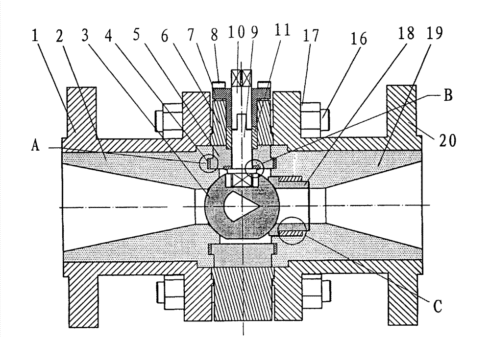
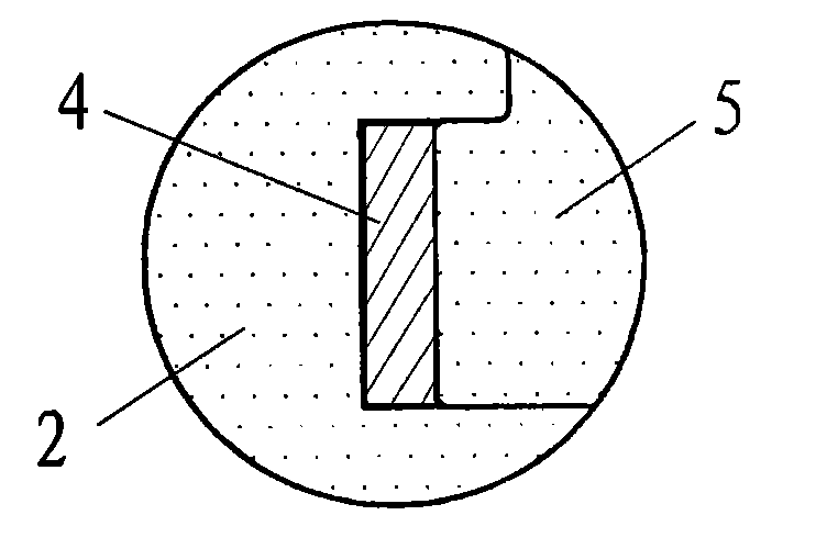
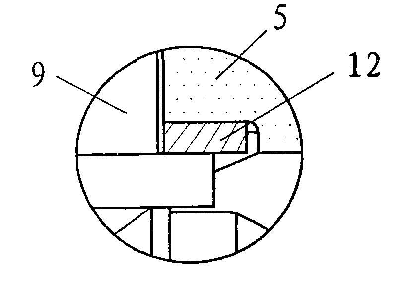
[0015] See Figure 1 to Figure 4 , the specific embodiment of the present invention is as follows: comprise left flange 1 and right flange 20, be provided with valve body 6 and valve inner liner 5 between left and right flanges (1, 20), bolt 16 and nut 17 connect left and right method The flange (1, 20) is fastened. The above structure is the basic structure of a general ball valve. The key is that the left flange 1 is provided with a left valve seat 2 made of ceramics and the right flange 20 is provided with a right valve seat 19 made of ceramics. The left and right valve seats (2, 19) are closely connected with the left and right flanges (1, 20) respectively and solidly connected to form a flange with a ceramic inner surface. The above-mentioned left and right valve seats (2, 19) and the left and right flanges (1 , 20) The connection method can be through adhesive bonding, or sintering or other conventional or existing methods after coating ceramics on the inner surface of t...


PUM


Abstract

The invention discloses a high-pressure high-temperature ceramic adjusting ball valve which is reliable in sealing, resistant to high pressure and high temperature, resistant to corrosion and capable of automatically adjusting sealing performance to certain extent. The adjusting ball valve comprises a left flange (1) and a right flange (20), a valve body (6) and a valve body liner (5) are arranged between the left flange (1) and the right flange (20), and the left flange (1) and the right flange (20) are fastened by a bolt (16) and a nut (17). The adjusting ball valve is characterized in that a left valve seat (2) made of ceramic is arranged in the left flange (1), a right valve seat (19) made of ceramic is arranged in the right flange (20), a ball (3) made of a ceramic material, playing a role in opening or closing a passage and provided with a V-shaped groove is disposed between the left valve seat (2) and the right valve seat (19), and connected with a valve rod (9) and an output shaft (10), the valve body liner (5) is made of a ceramic material, and a tenon-shaped sealing structure is formed between the valve body liner (5) and the left and right valve seats (2,19).

Description

Technical field: [0001] The invention relates to a regulating valve applicable to multiple fields, in particular to a novel ceramic regulating ball valve. Background technique: [0002] Regulating valve is a kind of valve widely used. It has good sealing, on-off and anti-blocking performance. It can make the flow path the simplest in use, can be adjusted without resistance and has the largest KV value. It also has good self-cleaning performance, It has many characteristics of simple and fast opening and closing and strong ability to overcome pressure difference. However, with the development of industrial technology, in petrochemical or various special application fields, the situation of the fluid in the pipeline is becoming more and more complicated, and the fluid contains various impurities. Or the transportation process involves environmental conditions such as high temperature, high pressure and high-speed flow, so the existing regulating valves are difficult to adapt t...

Claims


Application Information

Patent Timeline
IPC IPC(8): F16K5/06F16K5/08F16K27/06
CPCF16K5/0631F16K5/0668F16K5/0694F16K5/08F16K5/201F16K27/067
Inventor 金浩军季林举王秋光
Owner YANTAI KINGWAY SCI & TECH
Why Eureka
Try Eureka