Navigation path drawing method and terminal

A navigation path and terminal technology, applied in the information field, can solve problems such as large system resource occupation, affect user use, and prone to breakage, and achieve the effects of reducing resource occupation, improving drawing speed, and avoiding inaccuracy

Active Publication Date: 2014-04-09
YULONG COMPUTER TELECOMM SCI (SHENZHEN) CO LTD
View PDF5 Cites 8 Cited by
  • Summary
  • Abstract
  • Description
  • Claims
  • Application Information

AI Technical Summary

Problems solved by technology

[0002] When displaying the planned path between two points at a small scale, when the path is long, such as more than 1000KM, due to the large number of road nodes that need to be drawn and displayed, if the map drawing engine is used for drawing, the display speed will be very fast. Slow, difficult to meet the characteristics of embedded processing
[0003]

Method used


Image

  • Navigation path drawing method and terminal
  • Navigation path drawing method and terminal
  • Navigation path drawing method and terminal

Examples


Example Embodiment

[0031] In order to be able to understand the above objectives, features and advantages of the present invention more clearly, the present invention will be further described in detail below in conjunction with the accompanying drawings and specific embodiments. It should be noted that the embodiments of the application and the features in the embodiments can be combined with each other if there is no conflict.

[0032] In the following description, many specific details are set forth in order to fully understand the present invention. However, the present invention can also be implemented in other ways different from those described here. Therefore, the protection scope of the present invention is not limited to the specific details disclosed below. Limitations of the embodiment.

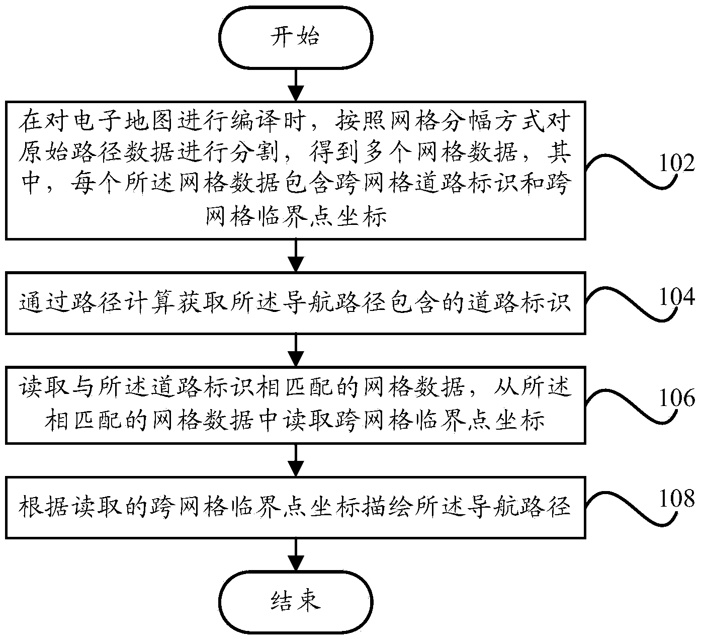
[0033] figure 1 A schematic flowchart of a method for drawing a navigation path according to an embodiment of the present invention is shown.

[0034] Such as figure 1 As shown, the navigation route drawi...


PUM


Abstract

The invention provides a navigation path drawing method and a terminal, wherein the navigation path drawing method comprises the steps of: when an electronic map is compiled, segmenting original path data in a grid amplitude separation manner, to obtain a plurality of grid data, wherein each grid data comprises a cross-grid road marking and cross-grid critical point coordinates; acquiring a road marking contained in the navigation path through path calculation; reading the grid data matched with the road marking, and reading the cross-grid critical point coordinates from the matched grid data; drawing the navigation path according to the red cross-grid critical point coordinates. Through the technical scheme, and when the navigation path is drawn, the resource occupation of a system can be reduced, the drawing speed of the navigation path can be improved, and the user experience can be favorably increased.

Description

Technical field [0001] The present invention relates to the field of information technology, and in particular to a method for drawing a navigation path and a terminal. Background technique [0002] When the planned path between two points is displayed on a small scale, when the path is longer, such as more than 1000KM, because there are more road nodes that need to be drawn and displayed, if the map drawing engine is used for drawing, the display speed will be very high. Slow, difficult to meet the characteristics of embedded processing. [0003] The current processing method is usually to thin out planned roads, but the degree of thinning is more difficult to control. For example, if the thinning is too large, the road shape is deformed and fracture is prone to occur, which does not match the actual situation. If the thinning is too small, right The compression of the number of road nodes is too small, the drawing engine is under too much pressure, the map display is too slow, w...

Claims


Application Information

Patent Timeline
IPC IPC(8): G01C21/34G01C21/26
CPCG01C21/32G01C21/3676
Inventor 顾立松
Owner YULONG COMPUTER TELECOMM SCI (SHENZHEN) CO LTD
Why Eureka
Try Eureka