Main shaft axial dynamic stiffness test device

A testing device and dynamic stiffness technology, applied in the direction of machine gear/transmission mechanism testing, etc., can solve the problems of difficult control and testing, low testing accuracy, and narrow application range.

Active Publication Date: 2014-04-09
XI AN JIAOTONG UNIV
View PDF7 Cites 19 Cited by
  • Summary
  • Abstract
  • Description
  • Claims
  • Application Information

AI Technical Summary

Problems solved by technology

[0009] In order to solve the existing problems of complex structure, difficult control and testing, narrow application range, and low test accuracy of existing devices for testing the axial dynamic stiffness of the spindle, the purpose of the present inventi

Method used


Image

  • Main shaft axial dynamic stiffness test device
  • Main shaft axial dynamic stiffness test device
  • Main shaft axial dynamic stiffness test device

Examples


Embodiment Construction

[0028] The present invention will be further explained below in conjunction with the drawings.

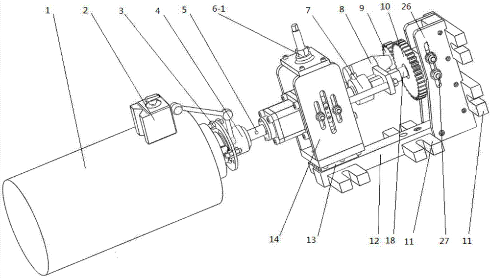
[0029] Reference figure 1 , A spindle axial dynamic stiffness test device, including a center height adjustment module, a force loading module, a displacement measurement module and a fixed support 12;

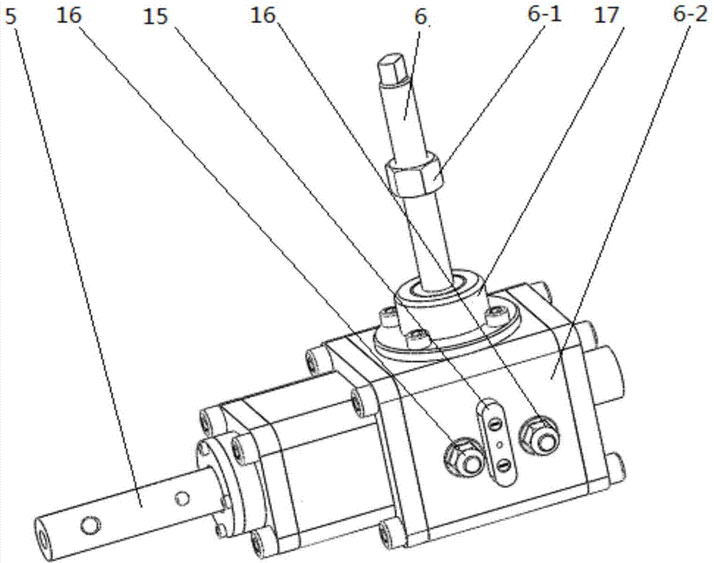
[0030] Reference figure 1 , figure 2 , Figure 4 The central height adjustment module includes a central height adjustment screw 6, a knob 6-1 is provided on the central height adjustment screw 6, and the central height adjustment screw 6 is mounted on the box 6-2 through a thrust ball bearing 17, and the box 6 -2 is connected with the first fixing plate 14 through the first lock nut 16, a butterfly spring 19 is arranged inside the box 6-2, and the butterfly spring 19 passes through the force sensor of the T-shaped force transmission part 7-1 and 7 connection, the force sensor 7 is connected to the guide element 7-2 of the force loading module;

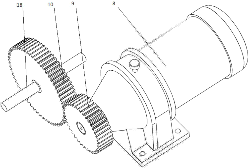
[0031] Reference image 3 , Figure 4 , ...


PUM


Abstract

The invention discloses a main shaft axial dynamic stiffness test device. A center height adjusting screw is arranged on a box body. A butterfly-shaped spring is arranged in the box body. The butterfly-shaped spring is connected with a force sensor. The force sensor is connected with a guide element of a force loading module. The guide element is connected with a feed screw. A displacement measurement module is arranged on a main shaft. A center height adjusting knob is adjusted. Through a connecting guide rod, the main shaft and test equipment are connected. After the displacement measurement module is arranged and adjusted, the displacement measurement module and a force measurement module access a computer, and test software is turned on. The main shaft is rotated, and the force loading module is started. The force loading module axially applies a corresponding pull pressure load on the main shaft. The test software synchronously acquires and records the applied pull pressure load and the corresponding axial displacement offset. After a procedure carries out data processing, a main shaft dynamic stiffness test result is output.

Description

Technical field [0001] The invention relates to the technical field of mechanical measurement, in particular to a testing device for the axial dynamic stiffness of a spindle. Background technique [0002] Machine tools are the most important basic mechanical equipment and working machine in the manufacturing industry, the cornerstone of industrial modernization, and an indispensable pillar in the development of the national economy. The spindle component is the key component of the machine tool, and its dynamic performance will directly affect the final processing performance of the machine tool. The dynamic performance of the spindle has an extremely significant impact on the working accuracy and vibration resistance of the spindle-bearing assembly system. The main evaluation index of the dynamic performance of the spindle is the dynamic stiffness, and the test of the axial stiffness of the spindle is of great significance in the dynamic stiffness test of the spindle and the eva...

Claims


Application Information

Patent Timeline
IPC IPC(8): G01M13/02
Inventor 朱永生闫柯洪军张进华张优云李建栋熊青青
Owner XI AN JIAOTONG UNIV
Why Eureka
Try Eureka