Resonant acceleration sensor device
An acceleration sensor and acceleration sensing technology, applied in the field of inertial navigation, can solve the problems of low excitation efficiency of single-sided electrodes, difficult electrode patterning, large dynamic impedance, etc., so as to overcome weak oscillation energy, reduce manufacturing difficulty and excitation efficiency. improved effect
- Summary
- Abstract
- Description
- Claims
- Application Information
AI Technical Summary
Problems solved by technology
Method used
Image
Examples
Embodiment 1
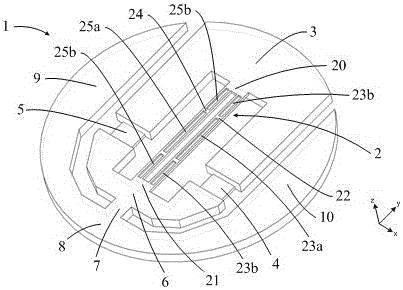
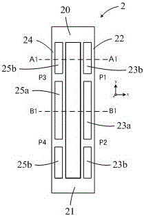
[0033] As a preferred embodiment of the present invention, such as Figure 2a As shown, the grooves on the front of the first vibrating beam 22 and the second vibrating beam 24 are three-the middle groove between the end grooves at both ends and the end grooves, the end groove and the middle groove The demarcation point coincides with the nodes (P1, P2, P3, P4) when the vibrating beam resonates, so as to improve the electrode excitation efficiency and resonance stability. The second excitation electrodes on the two side walls of the vibrating beam are divided into three corresponding independent sections to correspond to the first excitation electrodes inside the groove.
[0034] Such as Figure 2b and 2c As shown, the first excitation electrode on the inner wall of the groove at the end of the same vibrating beam is opposite to the polarity of the connection between the first excitation electrode on the inner wall of the middle groove and the excitation power supply. ...
Embodiment 2
[0037] Such as image 3 As shown, the difference between Embodiment 2 and Embodiment 1 is only that the fronts of the first vibrating beam 22 and the second vibrating beam 24 are provided with only middle grooves and no end grooves, that is, there is only one groove.
[0038] When the length of the vibrating beam is further shortened, if the front of the vibrating beam is made with the middle groove and the end groove at the same time, the difficulty of electrode patterning on the surface will increase, and the probability of short circuit between the first excitation electrode 26 and the second excitation electrode 27 will increase. Both the yield and the reliability of the manufacture of the resonant acceleration sensor device will be reduced. The vibrating beam structure in this embodiment is more suitable for the manufacture of resonant acceleration sensor devices with shorter vibrating beams.
Embodiment 3
[0040] Such as Figure 4 As shown, the difference between Embodiment 3 and Embodiment 1 is that the end grooves and the middle grooves on the front of the first vibrating beam 22 and the second vibrating beam 24 are integrated, and no excitation is made in the end grooves. electrode. To highlight the structural shape, Figure 4 Electrode patterns are not shown.
[0041] When the length of the vibrating beam is short, the boundary between the middle groove and the end groove on the front of the vibrating beam (near the node without groove) will greatly increase the influence on the excitation efficiency, reducing the resonance strength of the vibrating beam. By integrating the end groove and the middle groove on the front of the vibrating beam, the influence of the boundary on the excitation efficiency can be effectively reduced, and the resonance strength of the vibrating beam can be improved.
[0042] It can be seen that a groove is made on the front of the vibratin...
PUM
 Abstract
Description
Claims
Application Information
 - R&D
- Intellectual Property
- Life Sciences
- Materials
- Tech Scout
- Unparalleled Data Quality
- Higher Quality Content
- 60% Fewer Hallucinations
Browse by: Latest US Patents, China's latest patents, Technical Efficacy Thesaurus, Application Domain, Technology Topic, Popular Technical Reports.
© 2025 PatSnap. All rights reserved.Legal|Privacy policy|Modern Slavery Act Transparency Statement|Sitemap|About US| Contact US: help@patsnap.com


