Supercharge Your Innovation With Domain-Expert AI Agents!

Imaging lens assembly

An imaging system and lens group technology, applied in optical components, optics, instruments, etc., can solve the problems of eliminating aberration and distortion, undesigned configuration, and the difficulty of maintaining miniaturization of optical lens groups, so as to increase the image capture range, The control of color difference is flexible and the effect of shortening the total length

Active Publication Date: 2014-04-09
LARGAN PRECISION
View PDF6 Cites 27 Cited by
  • Summary
  • Abstract
  • Description
  • Claims
  • Application Information

AI Technical Summary

Problems solved by technology

[0003] Traditional miniaturized optical mirrors mounted on portable electronic products, as shown in US Patent No. 8,000,031, mostly use a five-piece lens structure. However, due to smart phones (Smart Phone) and PDA (Personal Digital Assistant) The popularity of high-end mobile devices has led to a rapid increase in the number of pixels and imaging quality of optical mirrors. The known five-piece optical mirrors will not be able to meet higher-level photography needs.
[0004] Although there is a further development of the six-piece optical lens group at present, as disclosed in U.S. Publication No. 2012 / 0170142, it is an optical lens group with six lenses, but it is not designed to configure one of the two lenses near the object side. With a negative refractive power and a strong positive refractive power lens, the back focal length of the optical mirror group cannot be effectively shortened, making it difficult to maintain the miniaturization of the total length of the optical mirror group under the premise of having a large viewing angle, let alone through the two lenses mutual compensation to eliminate aberrations and distortion

Method used


Image

  • Imaging lens assembly
  • Imaging lens assembly
  • Imaging lens assembly

Examples


no. 1 example

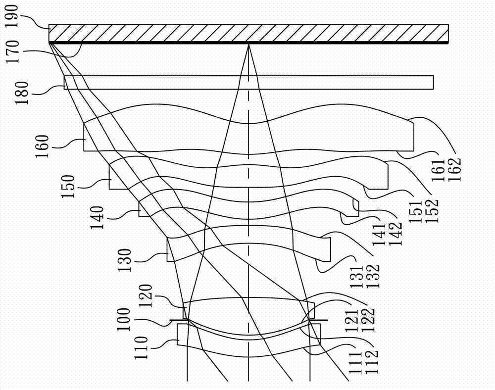
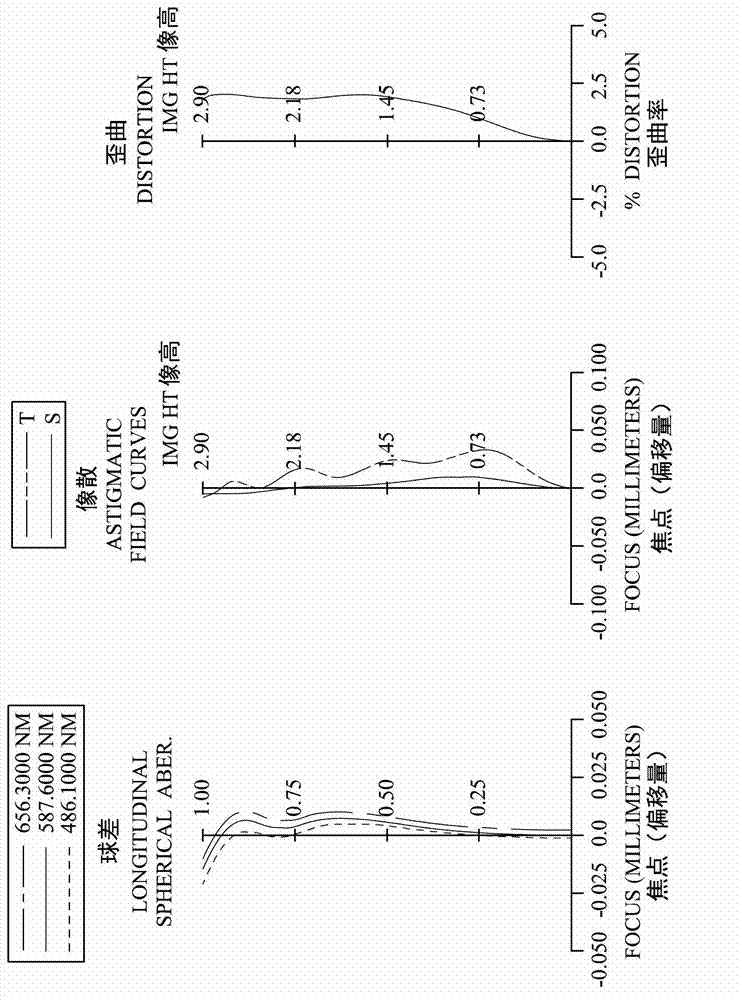
[0107] Please refer to figure 1 and figure 2 ,in figure 1 A schematic diagram showing a lens group of an imaging system according to the first embodiment of the present invention, figure 2 From left to right are the spherical aberration, astigmatism and distortion curves of the imaging system lens group of the first embodiment. Depend on figure 1 It can be seen that the image system lens group of the first embodiment includes the first lens 110, the aperture 100, the second lens 120, the third lens 130, the fourth lens 140, the fifth lens 150, and the sixth lens in order from the object side to the image side. A lens 160 , an IR filter (IR Filter) 180 , an imaging surface 170 and an image sensor 190 .

[0108] The first lens 110 is made of plastic material and has negative refractive power. The object-side surface 111 is convex, and the image-side surface 112 is concave, both of which are aspherical.

[0109] The second lens 120 is made of plastic material and has posit...

no. 2 example

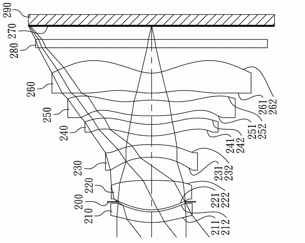
[0136] Please refer to image 3 and Figure 4 ,in image 3 A schematic diagram illustrating a lens group of an imaging system according to a second embodiment of the present invention, Figure 4 From left to right are the spherical aberration, astigmatism and distortion curves of the imaging system lens group of the second embodiment. Depend on image 3 It can be seen that the image system lens group of the second embodiment includes the first lens 210, the aperture 200, the second lens 220, the third lens 230, the fourth lens 240, the fifth lens 250, and the sixth lens in order from the object side to the image side. The lens 260 , the infrared filter 280 , the imaging surface 270 and the image sensor 290 .

[0137] The first lens 210 is made of plastic material and has negative refractive power. The object-side surface 211 is convex, and the image-side surface 212 is concave, both of which are aspherical.

[0138] The second lens 220 is made of plastic material and has ...

no. 3 example

[0153] Please refer to Figure 5 and Image 6 ,in Figure 5 A schematic diagram illustrating a lens group of an imaging system according to a third embodiment of the present invention, Image 6 From left to right are the spherical aberration, astigmatism and distortion curves of the imaging system lens group of the third embodiment. Depend on Figure 5 It can be seen that the image system lens group of the third embodiment includes the aperture 300, the first lens 310, the second lens 320, the third lens 330, the fourth lens 340, the fifth lens 350, and the sixth lens in order from the object side to the image side. The lens 360 , the infrared filter 380 , the imaging surface 370 and the image sensor 390 .

[0154] The first lens 310 is made of plastic material and has negative refractive power. The object-side surface 311 is convex, and the image-side surface 312 is concave, both of which are aspherical.

[0155] The second lens 320 is made of plastic material and has posi...


PUM


Abstract

An imaging lens assembly includes, in order from an object side to an image side, a first lens element, a second lens element, a third lens element, a fourth lens element, a fifth lens element and a sixth lens element. The first lens element with negative refractive power has a convex object-side surface and a concave image-side surface. The second lens element has positive refractive power. The third lens element has refractive power. The fourth lens element with refractive power has an object-side surface and an image-side surface being aspheric. The fifth lens element with positive refractive power has an object-side surface and an image-side surface being aspheric. The sixth lens element with negative refractive power has a concave image-side surface, wherein at least one reflection point is formed on the image-side surface thereof. The first lens element is configured with negative refractive power while the object end of the imaging lens assembly is configured with positive refractive power suchthat the image capturing range is increased, the spherical aberration reduced, and chromatic aberration can be flexibly adjusted and controlled.

Description

technical field [0001] The present invention relates to an image system lens group, and in particular to a miniaturized image system lens group applied to electronic products. Background technique [0002] In recent years, with the rise of portable electronic products with photography functions, the demand for miniaturized optical mirrors has been increasing, and the photosensitive elements of general optical mirrors are nothing more than charge coupled devices (CCD). Or Complementary Metal-Oxide Semiconductor Sensor (CMOS Sensor), and with the improvement of semiconductor process technology, the pixel size of the photosensitive element is reduced, and the miniaturized optical mirror group is gradually developing into the high-pixel field. Therefore, the requirements for image quality are also increasing. [0003] Traditional miniaturized optical mirrors mounted on portable electronic products, as shown in US Patent No. 8,000,031, mostly use a five-piece lens structure. How...

Claims


Application Information

Patent Timeline
Patent Type & Authority Applications(China)
IPC IPC(8): G02B13/18G02B13/00
CPCG02B9/60G02B9/62G02B13/00G02B13/0045G02B9/00G02B13/001G02B13/18G02B13/02G02B9/64
Inventor 许伯纶蔡宗翰黄歆璇
Owner LARGAN PRECISION
Features
  • R&D
  • Intellectual Property
  • Life Sciences
  • Materials
  • Tech Scout
  • Unparalleled Data Quality
  • Higher Quality Content
  • 60% Fewer Hallucinations
Learn More