Method and device for channel state information processing

An information processing method and channel state technology, applied in the field of communication, can solve the problem that UE measurement and feedback cannot adapt to various transmission methods, etc.

Active Publication Date: 2014-04-09
ZTE CORP
View PDF9 Cites 69 Cited by
  • Summary
  • Abstract
  • Description
  • Claims
  • Application Information

AI Technical Summary

Problems solved by technology

[0017] The technical problem to be solved by the present invention provides a channel state information processing method and device to solve the problem in the prior art that UE measurement and feedback cannot adapt to various transmission modes

Method used


Image

  • Method and device for channel state information processing
  • Method and device for channel state information processing
  • Method and device for channel state information processing

Examples


application example 1

[0126] In this example, the M1 first-type CSIs further include M11 A-subtype CSIs and M12 B-subtype CSIs, M1=M11+M12, and M11=M12, that is, the number of A-subtype CSIs and B-subtypes CSIs is equal .

[0127] Each A subclass CSI includes at least one or more precoding matrix indexes, used to indicate N T1 *v1 precoding matrix, N T1 is a positive integer greater than 1, v1 is a positive integer greater than or equal to 1; N T1 is the number of antenna ports, v1 is the number of layers;

[0128] Each B subclass CSI includes at least one or more precoding matrix indexes, which are used to indicate N T2 *v2 precoding matrix, N T2 is the number of transmit antennas or ports; N T2 is the number of antenna ports, v2 is the number of layers;

[0129] One or more precoding matrix indices of the A subclass indicate a codeword of a precoding matrix from the first codebook C1; one or more precoding matrix indices of the B subclass are from the first codebook C1 A codeword indicatin...

application example 2

[0138]In this example, the M1 first category CSIs have no subcategories. Each first type of CSI includes at least two types of precoding matrix indexes, that is, the first type of precoding matrix index and the second type of precoding matrix index, and the first type of precoding matrix index and the second type of precoding matrix index have their respective codebook.

[0139] One or more first-type precoding matrix indexes are used to indicate N T1 *v1's first precoding matrix, N T1 is the number of antenna ports, which is a positive integer greater than 1, and v1 is the number of layers, which is a positive integer greater than or equal to 1; the precoding matrix can represent the precoding matrix information of the first dimension of the two-dimensional rectangular antenna array; for example, it represents the horizontal Direction precoding matrix information;

[0140] One or more second-type precoding matrix indexes are used to indicate N T2 The second precoding matr...

application example 3

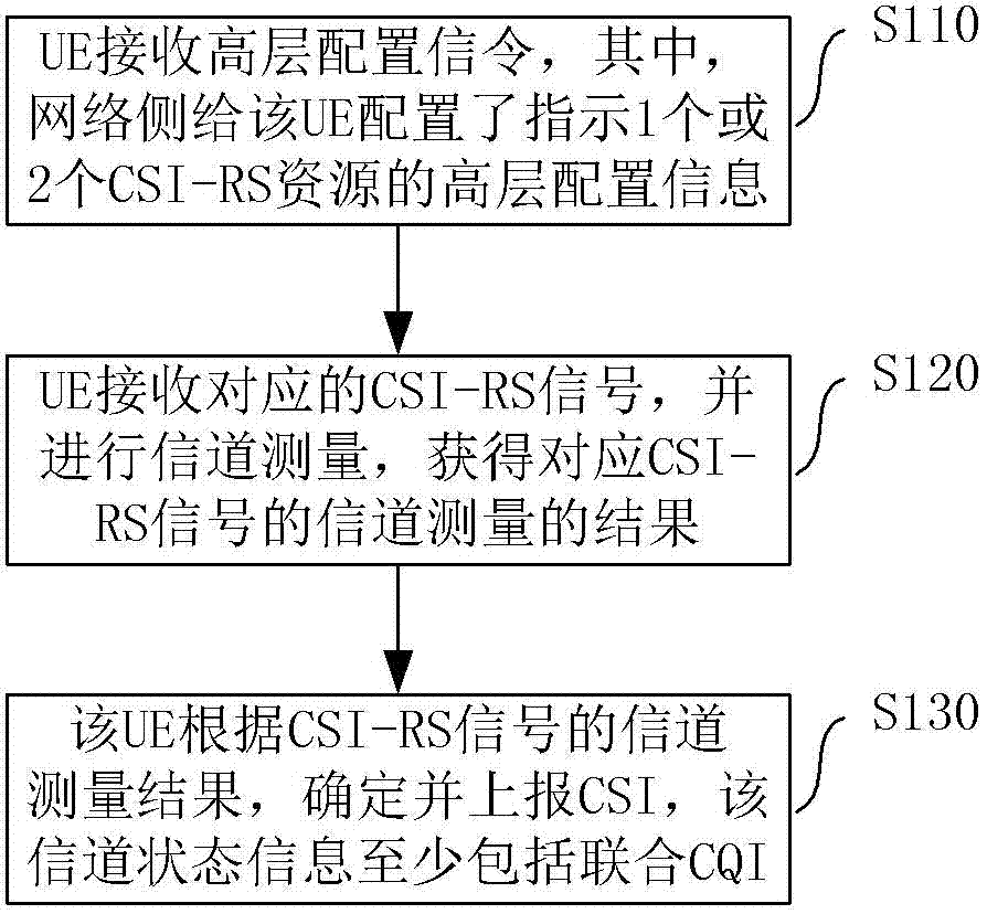
[0145] Step 1, according to multiple CSI-RS resources configured by a base station, receiving multiple CSI-RS signals on the multiple CSI-RS resources;

[0146] Step 2: Perform channel measurement in units of antenna groups, and report the CSI measured by each group of antennas, or report the CSI obtained by each group of antennas and the overall CSI calculated by calculating the CSI obtained by each group of antennas. The overall CSI includes Joint CQI.

[0147] If the three-dimensional beamforming technology is used, channel measurement can be performed with a group of antennas in the horizontal direction and a group of antennas in the vertical direction, and the PMI obtained by the horizontal antenna measurement and the PMI obtained by the vertical antenna measurement can be obtained respectively.

[0148] If the large-scale multiple-input multiple-output technology is adopted, channel measurement can be performed in units of groups, and the PMI measured by each group of an...


PUM


Abstract

The invention discloses a method and a device for channel state information processing in order to solve the problem that measurement and feedback of UE cannot adapt to all kinds of transmission modes in the prior art. The method comprises the following steps: UE receives high-level configuration information which is from a base station and indicates one or two CSI-RS resources; the UE receives a corresponding CSI-RS signal according to the high-level configuration information and carries out channel measurement to obtain a channel measurement result; and the UE determines and reports a CSI according to the channel measurement result of the CSI-RS signal, wherein the CSI at least includes a combined CQI which is calculated according to two pre-coding matrixes, and the two pre-coding matrixes are measured according to the CSI-RS signal of one base station. The device comprises a configuration information receiving module, a channel measuring module and a CSI processing module. By the adoption of the technical scheme of the invention, the capacity and spectrum efficiency of the existing system are greatly improved.

Description

technical field [0001] The present invention relates to the communication field, in particular to a method and device for processing Channel State Information (CSI for short). Background technique [0002] In the wireless communication technology, when the base station side (for example, an evolved Node B, eNodeB, eNB for short) uses multiple antennas to transmit data, spatial multiplexing can be adopted to increase the data transmission rate. That is, the sending end uses the same time-frequency resource to transmit different data at different antenna positions, and the receiving end (such as user equipment UE) also uses multiple antennas to receive data. [0003] In the case of a single user, all antenna resources are allocated to the same user, and this user exclusively occupies the physical resources allocated to the base station side within a transmission interval. This transmission method is called Single User Multiple Input Multiple Output (SMUMO). -Input Multiple-Ou...

Claims


Application Information

Patent Timeline
Patent Type & Authority Applications(China)
IPC IPC(8): H04B7/06H04W24/10
Inventor 徐俊陈艺戬肖华华孙云锋张峻峰
Owner ZTE CORP
Why Eureka
Try Eureka