Electric motor

A technology of electric motors and motor shafts, applied in the direction of electric components, electromechanical devices, electrical components, etc.

Inactive Publication Date: 2014-04-09
HANNING ELECTRO WERKE GMBH & CO KG
View PDF10 Cites 10 Cited by
  • Summary
  • Abstract
  • Description
  • Claims
  • Application Information

AI Technical Summary

Problems solved by technology

A disadvantage of this known electric motor is that the heat dissipation of the electronic components arranged in

Method used


Image

  • Electric motor
  • Electric motor
  • Electric motor

Examples


Embodiment Construction

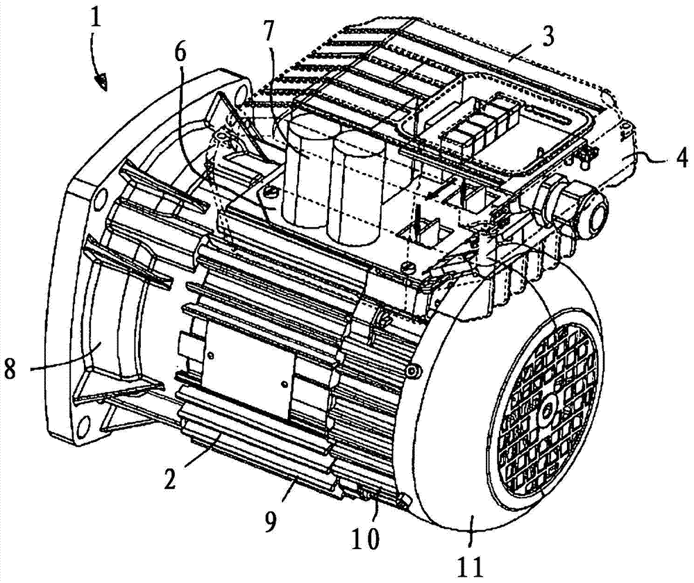
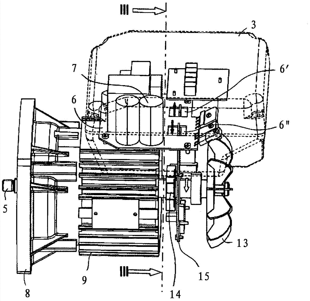
[0022] The electric motor 1 can be designed, for example, as a synchronous motor and comprises a housing 2 and a terminal box 3 which is fastened to the upper side of the circumferential wall of the housing 2 in a non-positive or form-fitting manner.

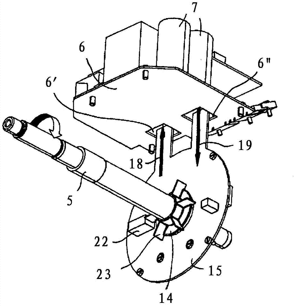
[0023] The terminal box 3 has a pot-shaped wall profile 4 , inside which extends a circuit board 6 extending parallel to the motor shaft 5 , said circuit board being equipped with electronic components 7 . The electronic components 7 arranged on the printed circuit board 6 can form a supply voltage input circuit structure and / or a rectifier.

[0024] The housing 2 of the electric motor 1 has an A-bearing end shield 8 , a housing central part 9 , a B-bearing end shield 10 and a fan housing 11 , which are arranged coaxially one behind the other in the axial direction. The motor shaft 5 is arranged in the housing 2 constructed in this way, the stator and the rotor are arranged in the area of ​​the housing central part 9 , the main ...


PUM


Abstract

The invention relates to an electric motor with a housing, in which a stator arranged coaxially to a motor shaft and a rotor are arranged, and with a terminal box arranged on a circumferential wall of the housing, with electronic components being arranged in said terminal box, wherein, firstly, an aperture is provided between the terminal box and the housing, and secondly, an auxiliary fan impeller, which is connected fixedly to the motor shaft, is provided in the housing, such that, during operation of the electric motor, an air flow can flow from an interior of the housing into an interior of the terminal box and/or vice versa.

Description

technical field [0001] The present invention relates to an electric motor having a housing and a junction box arranged on the peripheral wall of the housing, in which a stator and a rotor arranged coaxially with the motor shaft are arranged, in the junction box Set with electronic components. Background technique [0002] An electric motor is known from DE 10 2004 033 745 B4 with a housing and a terminal box arranged on the peripheral wall of the housing, in which terminal box electronic components are arranged. In order to dissipate the heat of the electronic components arranged in the terminal box to the surroundings, the lower part of the terminal box facing the housing is designed in a heat-conducting manner. A disadvantage of this known electric motor is that the heat generated by the power electronics components in the terminal box is dissipated slowly, since the components are not directly cooled by the air flow. [0003] Known from DE 10 2004 031 399 A1 is an elect...

Claims


Application Information

Patent Timeline
IPC IPC(8): H02K5/22H02K9/12H02K5/18
CPCH02K5/20H02K9/14H02K9/06H02K5/18H02K5/225F04B17/03H02K5/207
Inventor G·斯托克W·舍费尔H·托伊贝尔E·伯恩斯坦
Owner HANNING ELECTRO WERKE GMBH & CO KG
Why Eureka
Try Eureka