Self-cooling technology and machining method of metal plate spiral stepped blade twist drill

A processing method, twist drill technology, applied in twist drills, metal processing equipment, parts of boring machines/drilling machines, etc., can solve problems such as inability to achieve cooling effect, twist drills are not durable, and the hardness of the cutter head is reduced, so as to improve heat dissipation Effect, efficiency improvement, and effect of reducing cutting temperature

Inactive Publication Date: 2014-04-16
李仕清
View PDF8 Cites 3 Cited by
  • Summary
  • Abstract
  • Description
  • Claims
  • Application Information

AI Technical Summary

Problems solved by technology

[0002] At present, the twist drill used in mechanical processing is composed of chisel edge, cutting edge, helical minor cutting edge, and side edge. The cutting edge and helical minor cutting edge are roughly in a single structure, with poor centering structure and protruding to the outside of the helical surface. Parts are easy to break, these twist drills are extremely undurable, especially when drilling and milling workpieces with high hardness, a large amount of heat is generated, resulting in a decrease in the hardness of the cutter head, resulting in wear of the cutter head, and the cooling technology becomes the bottleneck of the tool use , it is difficult to inject the coolant directly into the cutting place with ordinary technology, and the ideal cooling effect cannot be achieved.

Method used


Image

  • Self-cooling technology and machining method of metal plate spiral stepped blade twist drill
  • Self-cooling technology and machining method of metal plate spiral stepped blade twist drill
  • Self-cooling technology and machining method of metal plate spiral stepped blade twist drill

Examples


Embodiment approach 1

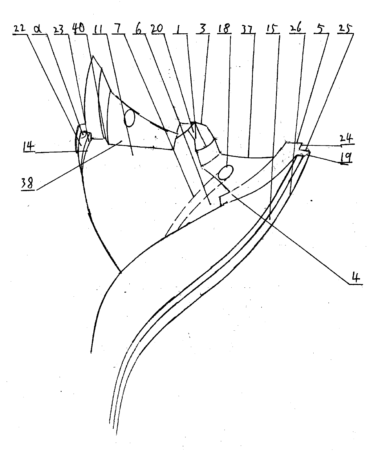
[0034] Such as figure 1 , Figure 7-Figure 10 , Figure 11-Figure 14 As shown, the self-cooling technology and processing method of the sheet metal spiral stepped edge twist drill of the first embodiment of the present invention mainly relate to the sheet metal twist drill used in mechanical processing, wherein, Figure 7 The drill point in the axial center is not chamfered, so the chisel edge is larger and the cutting resistance is also larger. Figure 8 Although the drill point in the axial center is chamfered, there is still a reduced chisel edge, and the cutting resistance is relatively Figure 7 reduced a lot, Figure 9-Figure 10 After chamfering, the drill point in the axial center has become a sharp edge without a chisel edge, and the cutting resistance is the smallest. Figure 11-Figure 12 A cooling hole 16 is set on the tapered shank 12 and straight shank 12 of the twist drill, and the other end of the cooling hole 16 is integrated with the tapered shank 12 and th...

Embodiment approach 2

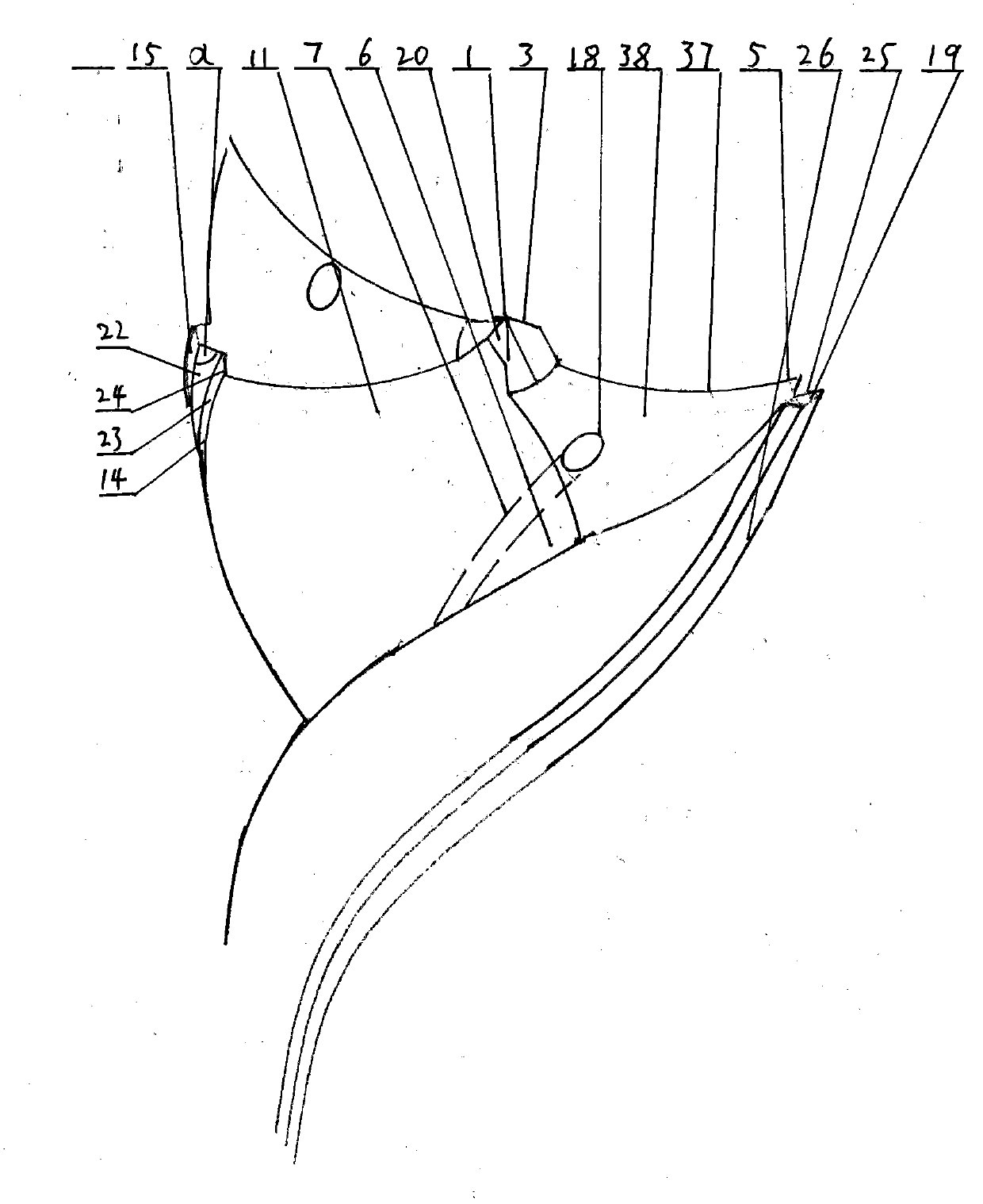
[0039] Such as figure 2 , Figure 7-Figure 10 , Figure 11-Figure 14 As shown in Embodiment 2, the self-cooling technology and processing method of the sheet metal spiral stepped edge twist drill of the second embodiment of the present invention and its processing method, on the basis of the first embodiment, the secondary cutting edge 37 of the present invention mainly functions To stabilize the cutting, the secondary cutting edge 37 and the main cutting edge 5 form an arc-shaped secondary cutting edge 37, that is, an arc-shaped edge or a curved edge, and extend to the rear cutting surface 4 to form a structure with an arc-shaped groove or groove , the angle between the main cutting edge 5 and the helical minor cutting edge 14 is less than 90°.

[0040] By setting the arc-shaped groove or groove on the rear cutting surface 4, the cutting stability and efficiency of the twist drill are improved, the cost is reduced, and resources are saved.

[0041] According to the above ...

Embodiment approach 3

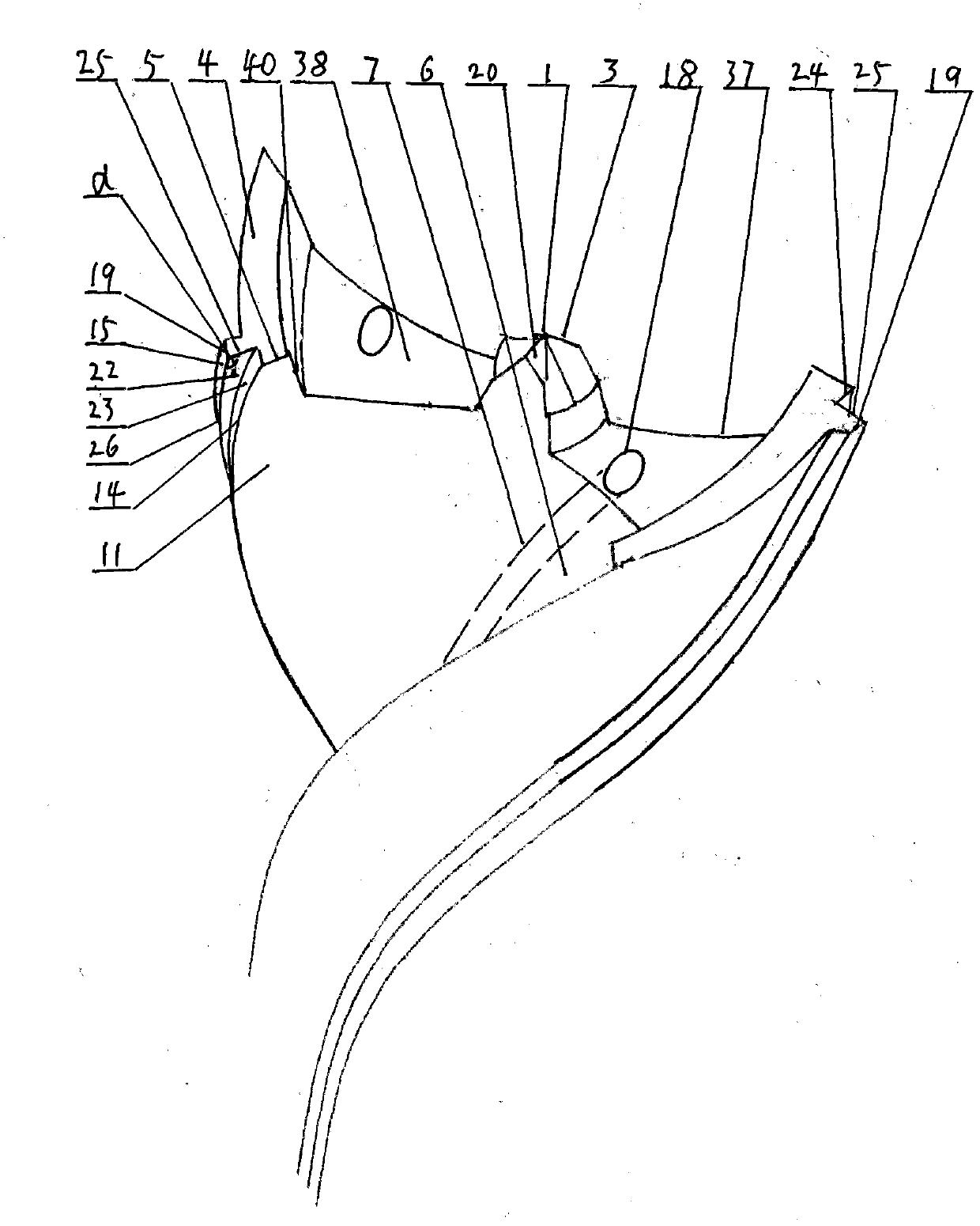
[0043] Such as image 3 , Figure 7-Figure 10 , Figure 11-Figure 14 As shown, the self-cooling technology and processing method of the sheet metal spiral stepped edge twist drill of the third embodiment of the present invention, on the basis of the first and second embodiments, the minor cutting edge 37 of the present invention mainly plays a role in stabilizing cutting The minor cutting edge 37 and the major cutting edge 5 form an arc-shaped minor cutting edge 37, that is, a trapezoidal edge, and extend to the rear cutting surface 4 to form a trapezoidal groove structure. The major cutting edge 5 and the helical minor cutting edge 14 The included angle is greater than 90°.

[0044] The cutting efficiency of the main cutting edge 5 is ensured by the included angle between the main cutting edge 5 and the helical minor cutting edge 14 being greater than 90°, and the setting of the trapezoidal groove 38 on the minor cutting edge 37 effectively prevents cutting obstruction and ...


PUM


Abstract

The invention provides a self-cooling technology and a machining method of a metal plate spiral stepped blade twist drill, and relates to a metal plate spiral stepped blade twist drill. The metal plate spiral stepped blade twist drill is characterized in that a sub spiral cutting edge is arranged on each spiral bar, a sub spiral cutting face is formed along the outer sides of the sub spiral cutting edges, a spiral cutting face is formed along the inner sides of the sub spiral cutting edges, a composite spiral cutting face with at least one step is formed on the spiral cutting face in a stepped protruding mode, the top face of the front end of the spiral cutting face is a rear cutting face, and the spiral cutting face or the composite spiral cutting face intersects with the rear cutting face to form a stepped cutting edge, namely a stepped blade; the back face corresponding to the spiral cutting face in the rotating direction of the metal plate spiral stepped blade twist drill is a rear spiral face, at least one spiral groove is formed in the rear spiral face, or a spiral table is formed on the two sides of the groove, or a cooling pipe is integrally arranged in the spiral groove, or a sealed spiral face is integrally arranged or welded on the spiral table, a cooling hole communicated with the spiral groove or the cooling pipe is formed in the handle of a tool at the top end of the spiral groove or the spiral table, and a connecting opening communicated with the outside is formed in the top end of the handle of in the handle.

Description

Technical field: [0001] The invention relates to a self-cooling technology and a processing method of a sheet metal spiral stepped edge twist drill and a processing method thereof, which are used in drilling machine processing and fitter maintenance. Background technique: [0002] At present, the twist drill used in mechanical processing is composed of chisel edge, cutting edge, helical minor cutting edge, and side edge. The cutting edge and helical minor cutting edge are roughly in a single structure, with poor centering structure and protruding to the outside of the helical surface. Parts are easy to break, these twist drills are extremely undurable, especially when drilling and milling workpieces with high hardness, a large amount of heat is generated, resulting in a decrease in the hardness of the cutter head, resulting in wear of the cutter head, and the cooling technology becomes the bottleneck of the tool use , It is difficult to inject the coolant directly into the c...

Claims


Application Information

Patent Timeline
IPC IPC(8): B23B51/06B23B51/02
CPCB23B51/06B23B51/02
Inventor 李仕清
Owner 李仕清
Why Eureka
Try Eureka