
Toolbar limiter of slitting machine

A technology of limiter and slitting machine, which is applied in metal processing and other directions, can solve the problems of large vibration of the tool bar and affect the cutting accuracy of the tool bar, and achieve the effect of improving cutting accuracy, simple structure and obvious effect.

Inactive Publication Date: 2014-04-16
夏云美
View PDF5 Cites 0 Cited by
  • Summary
  • Abstract
  • Description
  • Claims
  • Application Information

AI Technical Summary

Problems solved by technology

The cutter rod of the existing slitting machine vibrates greatly when rotating, especially the end of the cutter rod, which seriously affects the cutting accuracy of the cutter rod

Method used


Image

  • Toolbar limiter of slitting machine
  • Toolbar limiter of slitting machine

Examples


Embodiment Construction

[0015] The preferred embodiments of the present invention will be described in detail below in conjunction with the accompanying drawings, so that the advantages and features of the present invention can be more easily understood by those skilled in the art, so as to define the protection scope of the present invention more clearly.

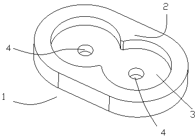
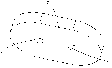
[0016] Such as Figure 1 to Figure 2 As shown, the cutter bar stopper 1 of the slitting machine of the present invention includes a one-piece stopper body 2, which is provided with an "8"-shaped stopper groove 3, and the stopper groove 3 is provided with a pair of fixed through holes 4.

[0017] The limiting body 2 is made of hard rubber.

[0018] It is not limited thereto, and any changes or replacements that do not go through creative efforts shall fall within the scope of protection of the present invention. Therefore, the protection scope of the present invention should be determined by the protection scope defined in the claims.


PUM


Abstract

The invention discloses a toolbar limiter of a slitting machine. The toolbar limiter of the slitting machine comprises a platy limit body, an 8-shaped limit groove is formed in the limit body, and a pair of fixing through holes is formed in the limiting groove. By the aid of the limit body made of hard rubber, a user can directly sleeve the 8-shapied limit groove at the tail end of a toolbar and fixes the toolbar in the fixing through holes, so that nuisance vibration of the tool bar is greatly reduced, and cutting precision of the slitting machine is improved. The toolbar limiter of the slitting machine is simple in structure, low in cost, obvious in effect and high in practicality.

Description

technical field [0001] The invention relates to a printing device, more precisely, it is a cutter bar limiter of a slitting machine. Background technique [0002] The slitting machine is a device for longitudinally cutting wide rolls of printing materials, generally using a strip-shaped knife bar for cutting. The cutter rod of the existing slitting machine vibrates greatly when rotating, especially the end of the cutter rod, which seriously affects the cutting accuracy of the cutter rod. Contents of the invention [0003] The present invention mainly solves the technical problems existing in the prior art, thereby providing a cutter bar limiter of a slitting machine. [0004] Above-mentioned technical problem of the present invention is mainly solved by following technical scheme: [0005] A cutter bar stopper for a slitting machine, the cutter bar stopper for a slitting machine includes a sheet-shaped stopper body, and an "8"-shaped stopper recess is provided on the st...

Claims


Application Information

Patent Timeline
Patent Type & Authority Applications(China)
IPC IPC(8): B26D7/00
Inventor 夏云美
Owner 夏云美
Learn More