A catalyst regeneration method for reducing carbon dioxide emissions

A carbon dioxide and catalyst technology, applied in the field of regeneration of carbon-containing catalysts, can solve problems such as high coke and dry gas yield, and achieve the effects of improving coke burning efficiency, reducing floor space and reducing carbon emissions

Active Publication Date: 2016-01-20
CHINA PETROLEUM & CHEM CORP +1
View PDF7 Cites 0 Cited by
  • Summary
  • Abstract
  • Description
  • Claims
  • Application Information

AI Technical Summary

Problems solved by technology

For example, the highest activity recovery of the regenerated catalyst can be achieved during regeneration, but when the regenerated catalyst participates in the reaction, it may cause high coke and dry gas yields due to its high activity, which is undesirable

Method used


Image

  • A catalyst regeneration method for reducing carbon dioxide emissions

Examples


Embodiment

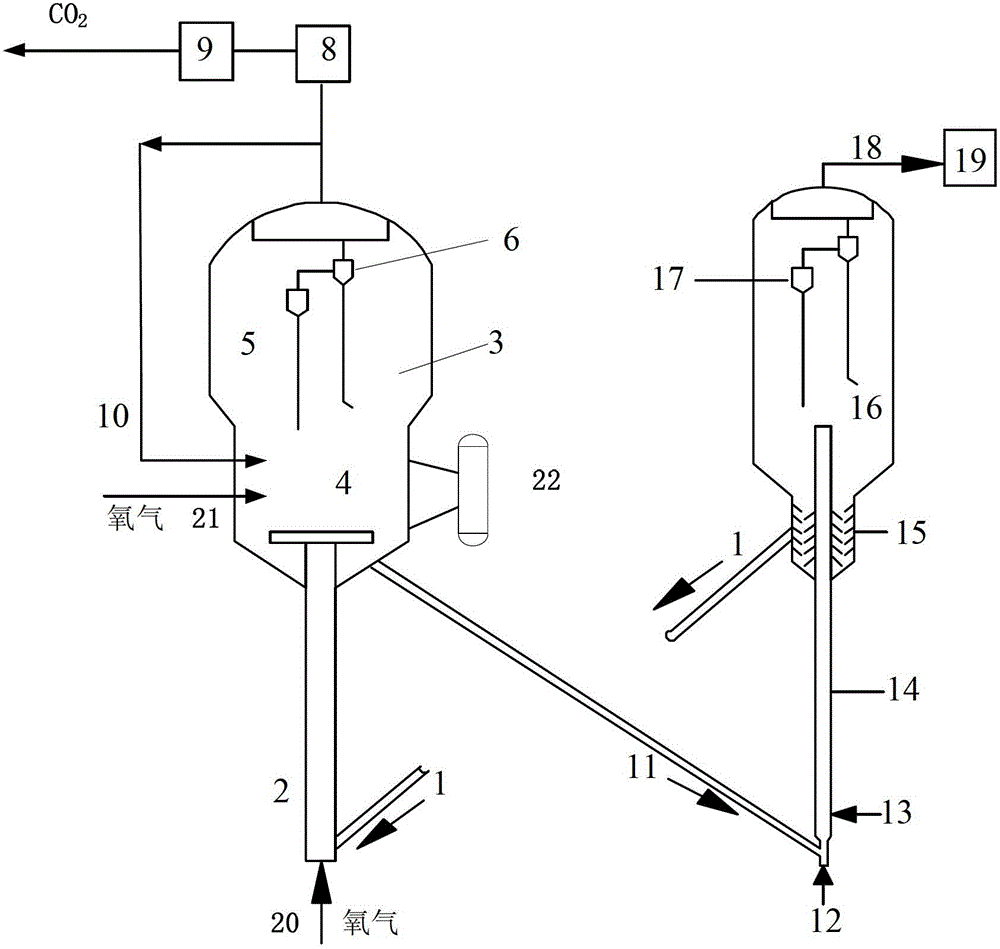
[0033] The embodiment is carried out on a catalytic cracking demonstration unit, as shown in the accompanying drawing. The demonstration plant does not have a flue gas energy recovery system and a carbon dioxide separation system. The inner diameter of the burnt tube is 5 cm, and the inner diameter of the dense-phase bed is 50 cm. The catalyst is regenerated according to the regeneration method proposed by the present invention. Pure oxygen gas is fed into the burnt tube and the dense-phase bed respectively, and at the same time, part of the flue gas from the cyclone separation system of the regenerator is returned to the bottom of the dense-phase bed. The temperature in the middle of the burnt tube is 640°C, and the temperature of the dense-phase bed in the regenerator is 650°C. The residence time of the catalyst in the burnt tube was 12 seconds, and the average residence time in the dense bed was 2 minutes. The superficial linear velocity of gas in the burnt tube is 1.5m / s...


PUM


Abstract

The invention discloses a catalyst regeneration method capable of reducing carbon dioxide discharge. The catalyst regeneration method is characterized in that a catalyst with coke goes up in a coke combustion pipe by being carried by pure oxygen and undergoes a coke combustion reaction, and the coke combustion ratio in a coke combustion pipe is in a range of 30-50%; the catalyst discharged from the coke combustion pipe is subjected to pure oxygen-based residual coke burning; after cyclone separation, flue gas is orderly fed into a flue gas energy recovery system and a carbon dioxide separation system; after carbon dioxide separation, a capturing process is carried out; and the regenerated catalyst is directly returned into a reactor for recycle. The catalyst regeneration method realizes complete regeneration of a catalyst and uniform distribution of catalyst activity so that coke as a catalytic cracking by-product and a dry gas yield are reduced. The catalyst regeneration method greatly reduces carbon emission and even realizes zero emission of carbon.

Description

technical field [0001] The invention relates to a method for regenerating carbon-containing catalysts in hydrocarbon processing. More specifically, the present invention relates to a catalyst regeneration method for realizing carbon dioxide emission reduction in the catalytic cracking process of heavy oil. Background technique [0002] Today, the development of the global oil refining industry is facing many challenges such as oil price fluctuations, the trend of worsening crude oil quality, improved oil product quality specifications, stricter requirements for energy conservation and emission reduction, and the rapid development of biofuels. Reducing carbon dioxide emissions and mitigating climate change have become the key factors for the oil refining industry to transform the economy. The way of growth and the only way to maintain sustainable development. In October 2009, the country announced the action goal of controlling greenhouse gas emissions, that is, by 2020, the...

Claims


Application Information

Patent Timeline
Patent Type & Authority Patents(China)
IPC IPC(8): C10G11/14
CPCY02P30/40
Inventor 许友好王新李首先龚剑洪
Owner CHINA PETROLEUM & CHEM CORP
Why Eureka
Try Eureka