Heating device of annular part and annular cavity of heating device

A technology of ring components and heating devices, which is applied in the maintenance of heating chambers, lighting and heating equipment, furnace components, etc., can solve the problems of increasing manufacturing costs, increasing the structural size of the main beam, and increasing the power of the fan drive motor, etc., to achieve The effect of reducing manufacturing costs, reducing heat energy waste, and reducing material consumption

Active Publication Date: 2014-04-16
BEIJING GOLDWIND SCI & CREATION WINDPOWER EQUIP CO LTD
View PDF4 Cites 3 Cited by
  • Summary
  • Abstract
  • Description
  • Claims
  • Application Information

AI Technical Summary

Problems solved by technology

[0005] 1) There is waste in the air flow path
[0006] As the radial dimension of the bearing increases, the space in the central area within the annular area of ​​the bearing component will also increase. When the radial dimension of the bearing increases to the order of several meters, when such a bearing component is heated, the central area The space is superfluous for the convective heat transfer between the bearing surface and the hot air, and there is a huge waste in the air flow path
At the same time, as the size of the bearing components increases, in order to make the air flow fully flow, the power of the drive motor of the fan also increases, and the power consumption also increases.
[0007] 2) There is a waste of materials in the manufacture of heating devices
At the same time, due to the enlargement of the overall structure, in order to ensure the strength, the size of the main beam structure of the heating furnace body will also increase, and the material consumption will further increase, thereby greatly increasing the manufacturing cost

Method used


Image

  • Heating device of annular part and annular cavity of heating device
  • Heating device of annular part and annular cavity of heating device
  • Heating device of annular part and annular cavity of heating device

Examples


Embodiment 1

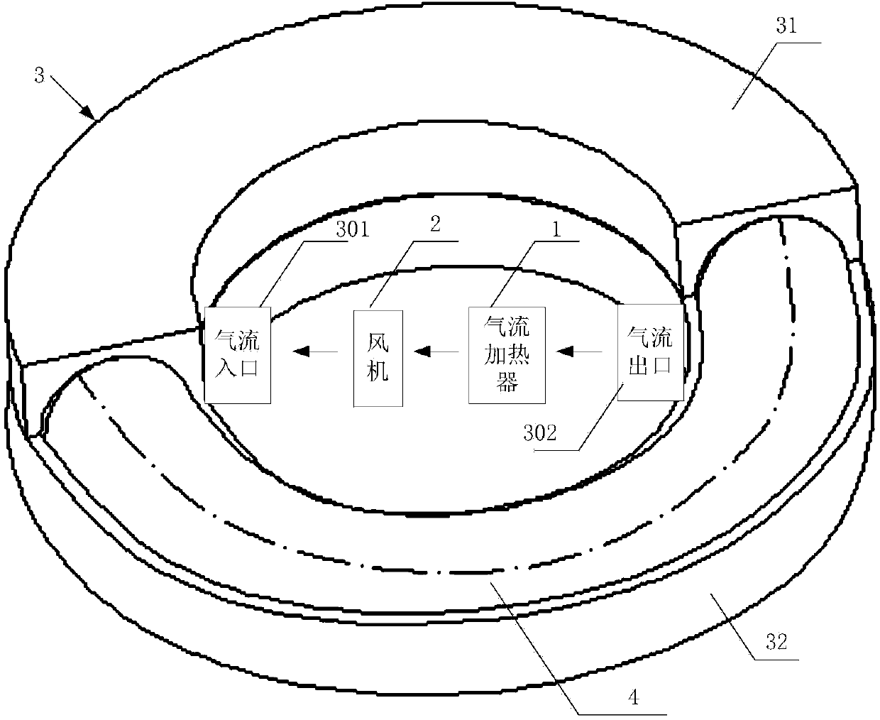
[0023] Such as figure 2 As shown, it is a structural schematic diagram of the heating device for the annular component in Embodiment 1 of the present invention. The heating device of the annular component of the present embodiment heats the annular component through the hot air flow, and it includes an airflow heater 1 and a fan 2, and also includes an annular cavity 3 for accommodating the annular component 4, and the outer wall of the annular cavity is provided with The airflow inlet 301 and the airflow outlet 302 , the airflow heater 1 heats the airflow, the fan 2 makes the airflow enter the airflow inlet 301 , and discharge from the airflow outlet 302 after passing through the airflow path in the annular cavity. In order to show the internal structure of the annular cavity 3, in figure 2 In , half of the upper annular cavity 31 is removed to show the state after the annular component 4 is put into the annular cavity 3 .

[0024] The structure of the heating device of t...

Embodiment 2

[0038] In addition to the improvement on the overall structure, the embodiment of the present invention further improves the interior of the annular cavity.

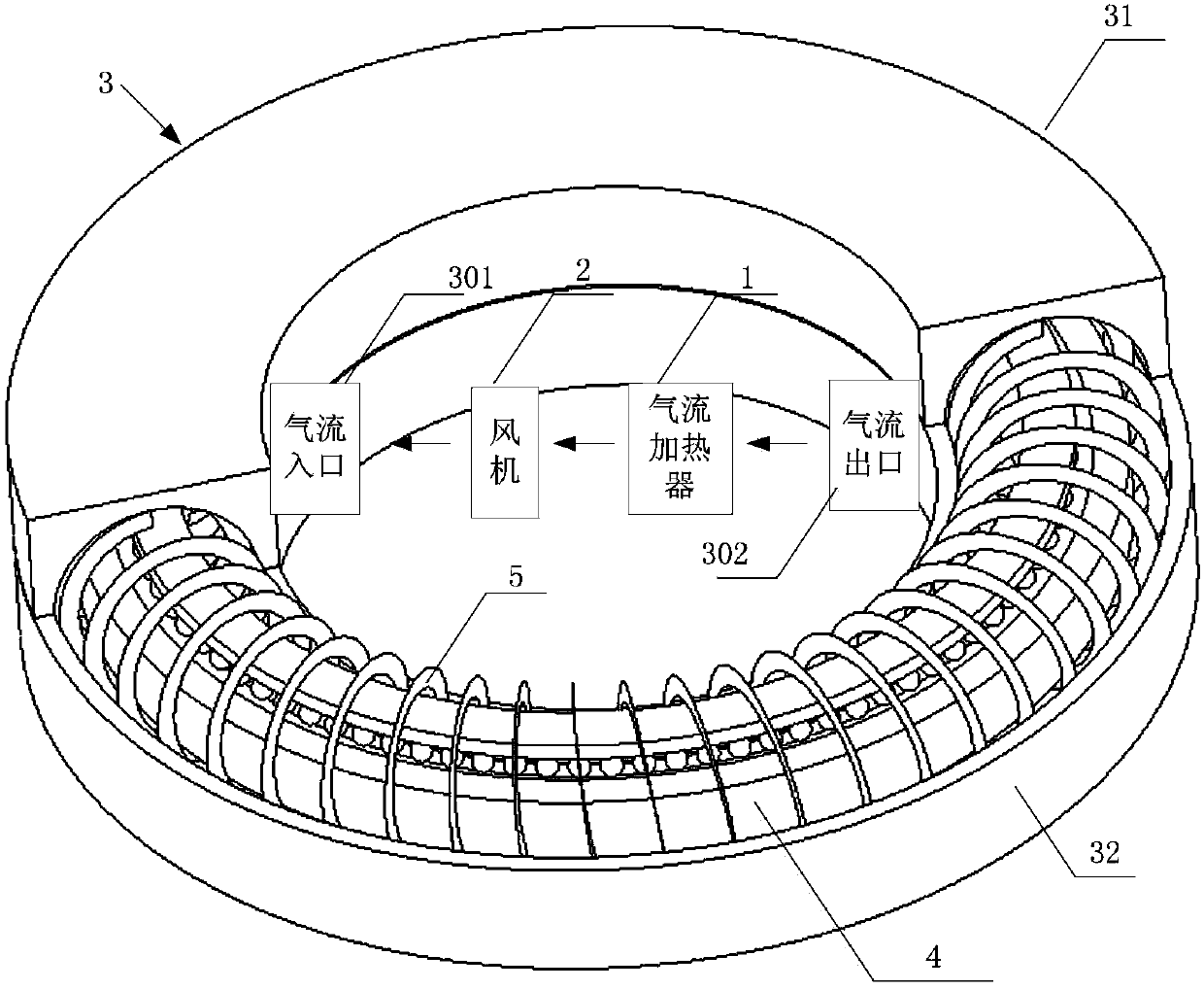
[0039] image 3 It is a structural schematic diagram of a heating device for an annular component in Embodiment 2 of the present invention, as image 3 As shown, on the basis of the first embodiment, a guiding body is provided in the annular cavity 3, and the guiding body makes the air flow move evenly along the surface of the annular component. By arranging the guide body in the annular cavity 3, the flow mode of the air flow is controlled, thereby making the annular component heated evenly and improving the heating efficiency.

[0040] Preferably, the guide body is a guide spiral fin 5, through which the guide spiral fin 5 makes the hot air flow trajectory into the annular cavity become around the ring part 4 (such as image 3 The solenoid-like movement of the large bearing part shown in ) heats the ring part 4 more ...

Embodiment 3

[0046] On the basis of the second embodiment, the present invention further improves the structure of the guide spiral fins 5, which will be described in detail below.

[0047] During the movement of the hot air from the air inlet 301 to the air outlet 302, the temperature will drop, and the heat exchange between the heated annular component 4 and the hot air will gradually decrease, resulting in uneven heating.

[0048] According to Newton's law of cooling,

[0049] Formula 1)

[0050] In this example, Be the heat exchange heat of hot air flow and the surface of ring part 4, A is the effective heat release area when hot air flow contacts with the surface of ring part 4, T is the temperature of hot air flow, Tw is the temperature of the surface of ring part 4, h is Surface heat transfer coefficient (also known as surface heat transfer rate). It can be seen from the formula (1) that A is a relatively fixed value, therefore, the heat exchange rate between the hot air flow ...


PUM


Abstract

The invention provides a heating device of an annular part. The heating device is used for heating the annular part through a thermal current and comprises a current heater and a fan, and further comprises an annular cavity for holding the annular part, a current inlet and a current outlet are formed in the outer wall of the annular cavity, the current heater is used for heating a current, the fan enables the current to enter the current inlet, and the current is discharged from the current outlet after passing through a current path in the annular cavity. According to the heating device, a current circulating path is saved, so that the current path can be concentrated near the annular part, and therefore, the heat exchange is more effective. Meanwhile, the material consumption during manufacturing the heating device is reduced, and the manufacture cost is lowered. In addition, the invention further correspondingly provides an annular cavity of the heating device. The annular cavity is used for holding the heated annular part, and the current inlet and the current outlet are formed in the outer wall of the annular cavity.

Description

technical field [0001] The invention relates to a heating device and its annular cavity, in particular to a heating device and its annular cavity which use gas as a heat exchange medium to heat an annular component. Background technique [0002] For the heating of large ring parts (for example, in the bearing shrink-fit method, large bearings need to be heated), oil bath, electromagnetic induction eddy current heating and air heating are generally used. Among them, the way of air heating is used more. Take the air heating furnace used in the bearing heat sleeve method as an example. The air heating furnace uses hot air as the heat transfer medium to heat the surface of the heat sleeve bearing parts. The heating method is mainly convective heat transfer, supplemented by radiation heat transfer. . [0003] Such as figure 1 As shown, it is a schematic structural diagram of an air heating furnace in the prior art, which shows the structure of a typical heating furnace for shr...

Claims


Application Information

Patent Timeline
Patent Type & Authority Applications(China)
IPC IPC(8): C21D9/40C21D1/34
CPCC21D1/34C21D1/767C21D9/40F27B17/00F27B17/0016F27B17/0083F27D7/04F27D2007/045F27B9/10F27B9/16F27D7/02
Inventor 马盛骏刘承前
Owner BEIJING GOLDWIND SCI & CREATION WINDPOWER EQUIP CO LTD
Why Eureka
Try Eureka