Mounting mechanism of continuous wall grab bucket

A technology for installing mechanisms and wall grabs, which is applied to earth movers/excavators, construction, etc., can solve problems such as low reliability and safety uncertainty, improve the overall structure and performance, improve safety, Effect of reduced pulling force requirements

Inactive Publication Date: 2014-04-16
李超
View PDF0 Cites 0 Cited by
  • Summary
  • Abstract
  • Description
  • Claims
  • Application Information

AI Technical Summary

Problems solved by technology

In addition, during the working process, these 8 bolts have to bear a weight of more than 12 tons, which requires the bolts to have sufficient strength, which brings uncertainty to safety, and the reliability of long-term use is not high.

Method used


Image

  • Mounting mechanism of continuous wall grab bucket
  • Mounting mechanism of continuous wall grab bucket

Examples


Embodiment Construction

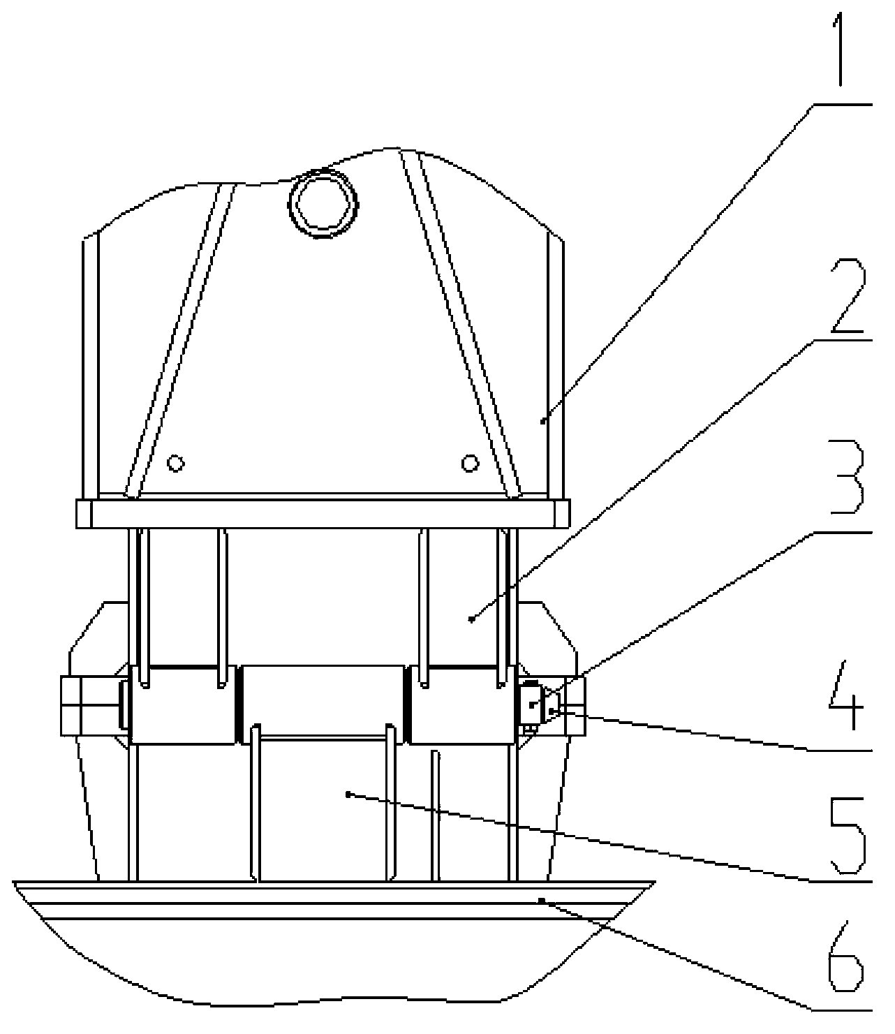
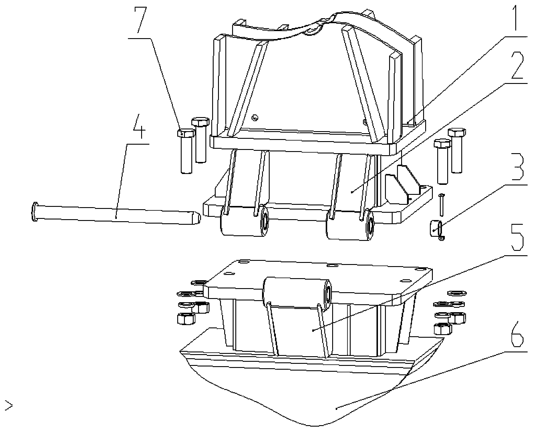
[0010] Such as figure 1 , figure 2 As shown, the installation mechanism of the diaphragm wall grab includes the lower section guide rod 1, the guide rod shaft sleeve 2 installed on the lower section guide rod 1, the grab body 6, the shaft sleeve 5 installed on the grab body, and the connecting pin 4. The pin positioning collar 3 and the connecting bolt 7 . The guide rod rotating shaft sleeve 2 is welded on the lower section guide rod 1. The rotating shaft sleeve 5 is welded on the grab body.

[0011] When assembling the grab, the grab body 6 and the lower section guide rod 1 are hinged with the connecting pin 4 through the guide rod shaft sleeve 2 on the lower section guide rod 1 and the shaft sleeve on the grab body 6, so that the When raising the mast, since the grab body 6 and the lower section guide rod 1 are hinged, the mast will get rid of the gravity of the grab when it is lifted, and the mast will be lifted to the final state first, and the guide rod is in the vert...


PUM


Abstract

The invention discloses a mounting mechanism of a continuous wall grab bucket and belongs to the field of piling machinery. The mounting mechanism comprises a lower guide rod and a grab bucket body, wherein guide rod rotating shaft sleeves are fixedly mounted on the lower guide rod, a rotating shaft sleeve is fixedly mounted on the grab bucket body, the grab bucket body and the lower guide rod are hinged together through the guide rod rotating shaft sleeves on the lower guide rod and the rotating shaft sleeve on the grab bucket body through a connecting pin shaft and a pin shaft locating sleeve ring, and the grab bucket body and the periphery of the lower guide rod are fixed through connecting bolts. The mounting mechanism has the advantages that the requirement for pull force of a variable-amplitude oil cylinder when a mast rises is greatly lowered, reliability and safety of grab bucket connection are improved, and maintenance, assembly and disassembly are convenient.

Description

technical field [0001] The invention belongs to the field of pile machinery, and in particular relates to an installation mechanism for a continuous wall grab. technical background [0002] At present, the installation of the diaphragm wall grab is mostly connected by bolts, and the grab body and the lower section guide rod are fixed with bolts. From the perspective of assembly requirements, the position of the eight light holes must be guaranteed to be installed correctly. This requires pairing processing during processing, which puts forward higher requirements for processing. From the point of view of the use process, the semi-guide rod type diaphragm wall needs to be installed with a grab first and then the mast is lifted. Since the grab and the guide rod are heavy, this requires a very large pulling force for the luffing cylinder, which is more demanding for the luffing cylinder. high. In addition, during the working process, these 8 bolts have to bear a weight of mo...

Claims


Application Information

Patent Timeline
Patent Type & Authority Applications(China)
IPC IPC(8): E02F5/14
Inventor 李超
Owner 李超
Why Eureka
Try Eureka