
Parallel-connection jacking pressure non-negative pressure water supply device

A water supply equipment, parallel technology, applied in the water supply main pipeline, water supply pipeline system, water supply pool configuration and other directions, can solve the problems of water pollution, bringing in other bacteria, and bubbles in the water in the tank.

Inactive Publication Date: 2014-04-16
SHANGHAI PANDA MACHINEGRP CO LTD
View PDF6 Cites 3 Cited by
  • Summary
  • Abstract
  • Description
  • Claims
  • Application Information

AI Technical Summary

Problems solved by technology

[0002] The superimposed pressure (no negative pressure) water supply equipment in the prior art is generally directly connected in series with the tap water for energy saving, and superimposed pressurized water supply is performed. When the water is insufficient, it will be supplemented by the reserved water in the tank. The current practice is to set the suction and exhaust valve on the tank to enter the air, or pre-charge the compressed gas, so as to alleviate the vacuum generation after the stored water in the tank drops. But the disadvantage of this method is 1. If the suction and exhaust valves are installed to enter the air, the pressure in the tank will drop to zero and the pressure of the tap water will drop to zero. This is not allowed by the water company because it affects the safety of public water supply. At the same time, the outside air will bring in other bacteria, etc., which will easily cause water pollution; 2. If the pre-charged compressed gas can maintain the tap water pressure, but when the compressed gas is released into the tank, it will easily cause the water in the tank to generate bubbles. Air bubbles enter the pump body with the water flow, making the pump unable to work normally and stop the water supply. At the same time, the compressed gas cannot be recovered after being released, so the equipment can only be used once

Method used


Image

  • Parallel-connection jacking pressure non-negative pressure water supply device
  • Parallel-connection jacking pressure non-negative pressure water supply device

Examples


Embodiment Construction

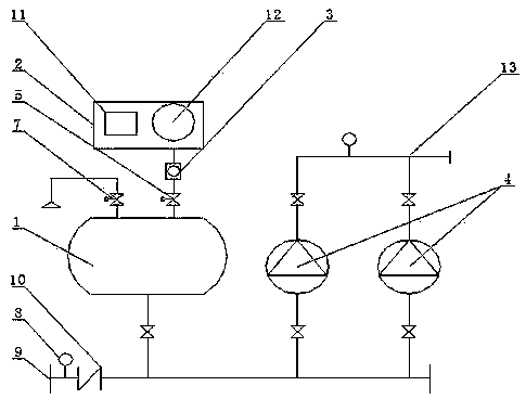
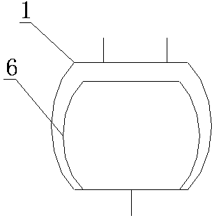
[0009] Such as figure 1 The shown parallel top pressure stacked water supply equipment consists of: water storage tank 1, inflation device 2, pressure reducer 3, water pump 4, controller 5, exhaust device 7, tap water volume detection device 8 and control cabinet (not shown in the figure) standard) and connecting pipes. The water pump 4 and the water storage tank 1 are connected in parallel with the tap water inlet 9 through a pipeline, and a one-way valve 10 is installed at the tap water inlet 9, and the tap water volume detection device 8 is installed between the tap water inlet 9 and the one-way valve 10. The device 7 is connected to the water storage tank 1, the inflator 2 is provided with an air compressor 11 and an air storage tank 12, the air storage tank 12 is connected with the water storage tank 1 after passing through the pressure reducing valve 3 and the controller 5, the outlet of the water pump 4 and the The water outlet main pipe 13 is connected, and the water ...


PUM


Abstract

Disclosed is a parallel-connection jacking pressure overlying water supply device. When the device works and tap water feeding pressure is normal and can meet the using requirement of a water pump, the water pump automatically works to supply water in an overlapping and pressurization mode so as to meet the using requirement of a user, an air exhaust device connected with a water storage tank is opened to enable tap water to enter the water storage tank for storage, and the air exhaust device is closed after the water storage tank is filled with water. When the flow quantity of the tap water cannot meet the using requirement of the water pump, an air inflation device automatically operates, a controller is started at the same time, high-pressure air enters the water storage tank, and the water stored in the tank is pushed to flow to the water pump completely, so that the water stored in the tank and the tap water are supplied to the water pump simultaneously, and the problem that the flow quantity of the tap water is not enough is solved. After the tap water recovers, the air exhaust device is automatically opened, the tap water enters the water storage tank again for storage, and the steps are executed in cycles.

Description

technical field [0001] The invention relates to a stacked water supply equipment, in particular to a parallel top pressure stacked water supply equipment. Background technique [0002] The superimposed pressure (no negative pressure) water supply equipment in the prior art is generally directly connected in series with the tap water for energy saving, and superimposed pressurized water supply is performed. When the water is insufficient, it will be supplemented by the reserved water in the tank. The current practice is to set the suction and exhaust valve on the tank to enter the air, or pre-charge the compressed gas, so as to alleviate the vacuum generation after the stored water in the tank drops. But the disadvantage of this method is 1. If the suction and exhaust valves are installed to enter the air, the pressure in the tank will drop to zero and the pressure of the tap water will drop to zero. This is not allowed by the water company because it affects the safety of pu...

Claims


Application Information

Patent Timeline
IPC IPC(8): E03B11/16E03B7/07
Inventor 池学聪谭红全
Owner SHANGHAI PANDA MACHINEGRP CO LTD
Learn More