Post-tensioning prestress hole cleaning and reeving device and method

A technology of post-tensioning prestressing and channeling, which is applied in the direction of construction, building structure, and building material processing, and can solve problems such as poor construction quality and progress, inability to complete cable threading work, and low efficiency of manpower cable threading, etc., to achieve The rope threading method saves labor, the threading quality is easy to guarantee, and the effect of saving the threading time

Inactive Publication Date: 2014-04-16
CHINA RAILWAY 13TH BUREAU GRP 6TH ENG COMPANY
View PDF7 Cites 0 Cited by
  • Summary
  • Abstract
  • Description
  • Claims
  • Application Information

AI Technical Summary

Problems solved by technology

[0002] At present, in the process of civil engineering construction, due to the influence of its construction technology, it is necessary to reserve prestressed reinforcement channels in the component body when prefabricating components. ) two hole-forming processes, and no matter which method is used to form holes, there will be phenomena such as the local section of the hole becoming smaller or blocked due to improper operation, resulting in low efficiency of manpower threading or failure to complete the threading work. In this case , the usual solution is to find the problematic part of the tunnel, and then apply prestress after excavation, dredging, and repair. This method has a long cycle, difficult quality control, and serious damage to the beam body, which has brought adverse consequences to the construction quality and progress of the project. and increased construction costs

Method used


Image

  • Post-tensioning prestress hole cleaning and reeving device and method
  • Post-tensioning prestress hole cleaning and reeving device and method
  • Post-tensioning prestress hole cleaning and reeving device and method

Examples


Embodiment 1

[0026] The present invention will be further described below in conjunction with accompanying drawing:

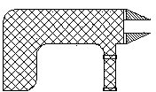
[0027] As shown in the figure, 1 is a power unit, 2 is a connecting rod, 3 is a cable drill rod, and 4 is a drill bit.

[0028] The invention consists of a power unit (1), a connecting rod (2), a cable drill rod (3) and a drill bit (4).

[0029] When cleaning the hole, insert the square cylindrical end of the connecting rod 2 into the lock of the power unit 1, and tighten the lock so that the power unit 1 and the connecting rod 2 are tightly connected; insert the cable drill rod 3 into the hollow cylindrical end of the connecting rod 2, Squeeze the hollow cylindrical end to tightly connect the connecting rod 2 and the cable drill rod 3; insert the other end of the cable drill rod 3 into the hollow cylindrical end of the drill bit 4, and squeeze the hollow cylindrical end to make the cable drill rod 3 and the drill bit 4 tightly connect. Start the power unit 1 to make ...


PUM


Abstract

The invention discloses a post-tensioning prestress hole cleaning and reeving device and method, and belongs to the technical field of engineering construction facilities. The device is characterized in that one end of a connecting rod is in a shape of a four-edge tetragonal prism, and the other end is hollow and cylindrical; the end of tetragonal prism is tightly connected with a power device in an inserted manner, and the hollow and cylindrical end is tightly connected with a cable type drilling rod in an inserted manner; the cable type drilling rod is a low-relaxation unbonded prestressed steel strand with strength and toughness; the drill bit is in a semi-hollow cylindrical structure and is tightly connected with the cable type drilling rod in an inserted manner, the non-hollow end is cylindrical, and outer diameter of the cylindrical end is larger than that of the hollow end. The device has the advantages that destroys on an existing structure are reduced to the utmost extent, and construction quality of post-tensioning prestress can be guaranteed effectively; the reeving method is time saving and force saving; reeving quality can be guaranteed easily; application range is wide, and construction cost is low; structure is simple and operation is facilitated; the device is simple in structure and convenient to operate, and ordinary workers can operate the device to perform construction after simple training.

Description

technical field [0001] The invention belongs to the technical field of engineering construction facilities, and relates to an improvement of a prefabricated component manufacturing tool and a manufacturing method. Background technique [0002] At present, in the process of civil engineering construction, due to the influence of its construction technology, it is necessary to reserve prestressed reinforcement channels in the component body when prefabricating components. ) two hole-forming processes, and no matter which method is used to form holes, there will be phenomena such as the local section of the hole becoming smaller or blocked due to improper operation, resulting in low efficiency of manpower threading or failure to complete the threading work. In this case , the usual solution is to find the problematic part of the tunnel, and then apply prestress after excavation, dredging, and repair. This method has a long cycle, difficult quality control, and serious damage to...

Claims


Application Information

Patent Timeline
Patent Type & Authority Applications(China)
IPC IPC(8): E04G21/12
Inventor 刘宏宇李志辉刘金山张庆
Owner CHINA RAILWAY 13TH BUREAU GRP 6TH ENG COMPANY
Why Eureka
Try Eureka