Two-stage centrifugal compressor and method for providing air for static pressure gas bearings of two-stage centrifugal compressor
A centrifugal compressor and compressor technology, applied to machines/engines, parts of pumping devices for elastic fluids, mechanical equipment, etc., can solve the problem of reducing system reliability and performance, increasing system complexity, and increasing maintenance costs and other issues to achieve the effect of increasing service life, improving reliability and performance, and reducing maintenance costs
- Summary
- Abstract
- Description
- Claims
- Application Information
AI Technical Summary
Problems solved by technology
Method used
Image
Examples
Embodiment 1
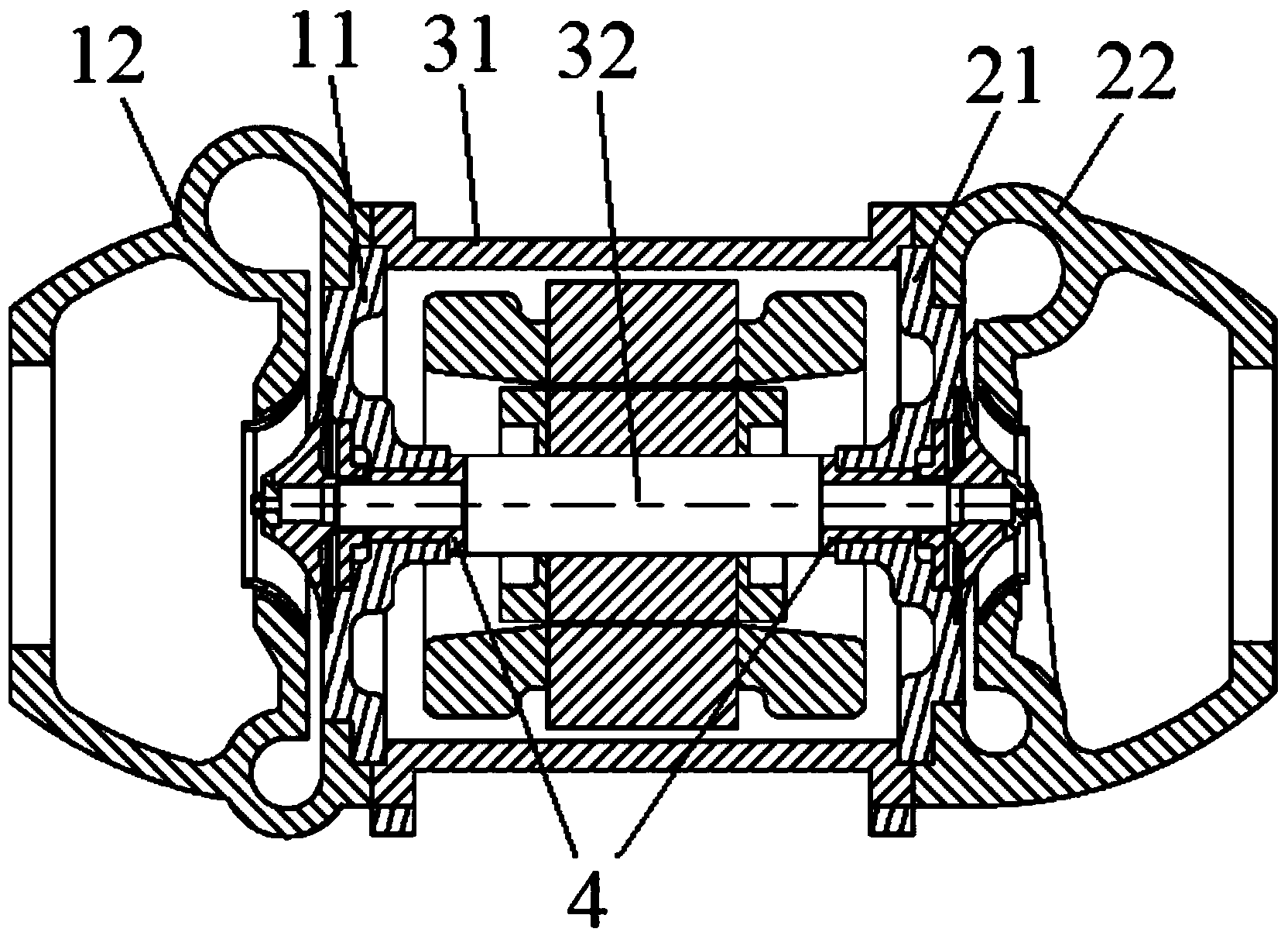
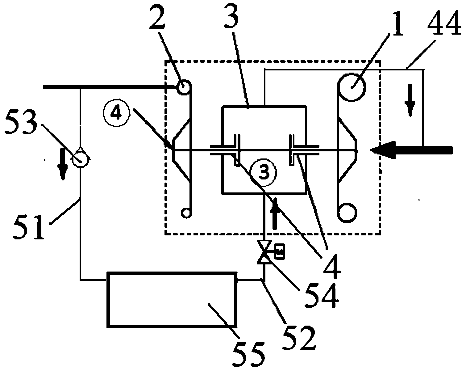
[0064] refer to Figure 1-5 , this embodiment provides a two-stage centrifugal compressor, including a motor 3, a first-stage compressor 1 and a second-stage compressor 2, and the first-stage compressor 1 includes a first base 11 and a first shell Body 12; the second-stage compressor 2 includes a second base 21 and a second housing 22;
[0065] The motor 3 includes a motor housing 31 and a motor rotor 32 disposed in the motor housing 31, and the motor rotor 32 includes a first output end and a second output end;
[0066] The first housing 12 and the second housing 22 are respectively fixed at both ends of the motor housing 31;
[0067] The first base 11 and the second base 21 are respectively fixed on the first housing 12 and the second housing 22;
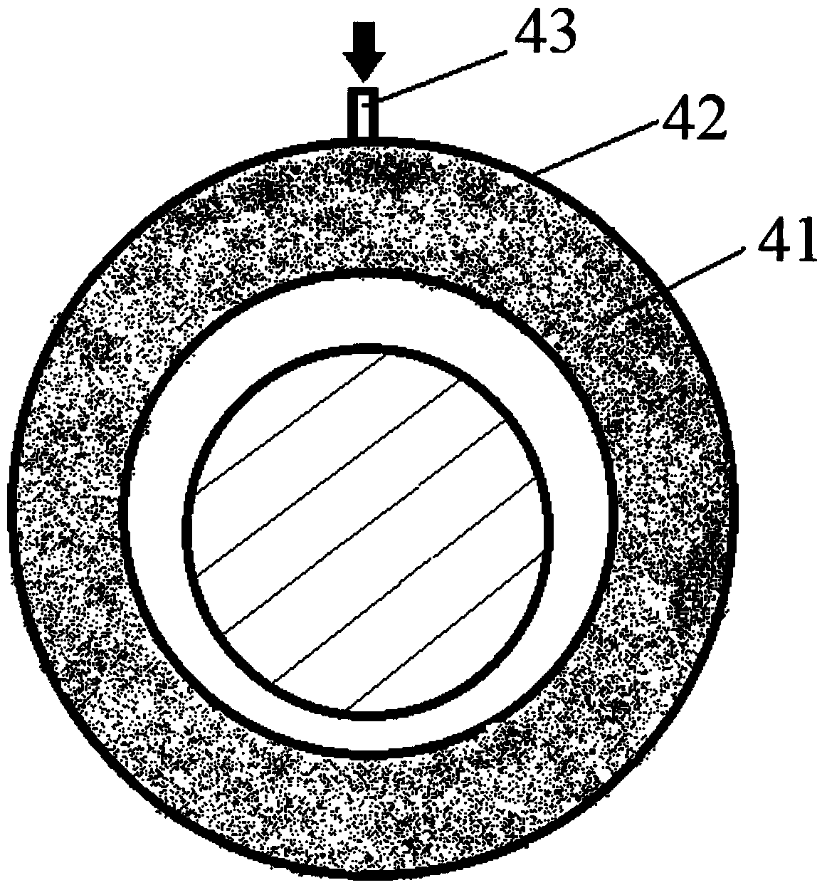
[0068] The first output end and the second output end of the motor rotor 32 are rotatably arranged on the first base 11 and the second base 21 respectively through the static pressure air bearing 4 .
[0069] The two-stage cent...
Embodiment 2
[0084] Reference attached Figure 1-5 , the present embodiment provides a method of utilizing the above-mentioned air supply device to supply air to the centrifugal compressor, comprising the following steps:
[0085] 1) When the gas pressure in the second air intake pipeline 513 is lower than the pressure threshold; the pressure threshold is determined according to the gas supply pressure when the static pressure air bearing 4 works stably.
[0086] S10: start the pump 57, the pump 57 extracts the liquid refrigerant from the first condenser 56, decompresses through the throttling orifice 528, part of the liquid refrigerant is vaporized, and the refrigerant gas and the remaining The liquid refrigerant mixture is sent into the gas-liquid separation tank 510;
[0087] S20: In the gas-liquid separation tank 510, the liquid refrigerant is stored in the liquid area of the gas-liquid separation tank 510, and the refrigerant gas enters the gas area on the upper part of the gas-liq...
Embodiment 3
[0099] Reference attached Figure 1-5 , the present embodiment provides a method of utilizing the above-mentioned air supply device to supply air to the centrifugal compressor, comprising the following steps:
[0100] 1) When the gas pressure in the third air intake pipeline 526 is lower than the pressure threshold; the pressure threshold is determined according to the gas supply pressure when the static pressure air bearing 4 works stably.
[0101] a1) Open the fourth throttle valve 519 and the fifth throttle valve 520;
[0102] b1) Make the liquid refrigerant at the bottom of the second condenser 518 enter the heating tank 521 through the fourth throttle valve 519;
[0103] c1) When the liquid level of the liquid refrigerant in the heating tank 521 is the same as the liquid level of the liquid refrigerant in the second condenser 518, close the fourth throttle valve 519 and the fifth throttle valve 520;
[0104] d1) start heating the heater 522, thereby vaporizing the liqui...
PUM
 Abstract
Description
Claims
Application Information
 - R&D
- Intellectual Property
- Life Sciences
- Materials
- Tech Scout
- Unparalleled Data Quality
- Higher Quality Content
- 60% Fewer Hallucinations
Browse by: Latest US Patents, China's latest patents, Technical Efficacy Thesaurus, Application Domain, Technology Topic, Popular Technical Reports.
© 2025 PatSnap. All rights reserved.Legal|Privacy policy|Modern Slavery Act Transparency Statement|Sitemap|About US| Contact US: help@patsnap.com


