
Gas-hydraulic coupling shock isolator

An isolation device and gas-liquid coupling technology, which is applied in the direction of gas-liquid shock absorbers, springs, shock absorbers, etc., can solve the problems of equipment accessory connection piping and cable damage, equipment malfunction, low acceleration and displacement, etc. , to achieve the effect of improving impact resistance, rapid linkage and compact connection

Inactive Publication Date: 2015-08-05
NAVAL UNIV OF ENG PLA
View PDF4 Cites 0 Cited by
  • Summary
  • Abstract
  • Description
  • Claims
  • Application Information

AI Technical Summary

Problems solved by technology

However, although this method can reduce the absolute acceleration response amplitude of the isolated equipment, the acceleration reduction is often at the expense of a large relative displacement of the equipment. Excessive relative displacement of the equipment may cause The damage to the system and cables will cause the equipment to not work normally, so a limiter must be used to limit the relative displacement
In some strong impact occasions (shock waves generated by underwater non-contact explosions), the acceleration and displacement that the equipment can withstand are very low, and the use of general elastic elements and stoppers cannot meet the requirements.

Method used


Image

  • Gas-hydraulic coupling shock isolator
  • Gas-hydraulic coupling shock isolator
  • Gas-hydraulic coupling shock isolator

Examples


Embodiment Construction

[0020] The present invention will be further described in detail below in conjunction with the accompanying drawings and specific embodiments.

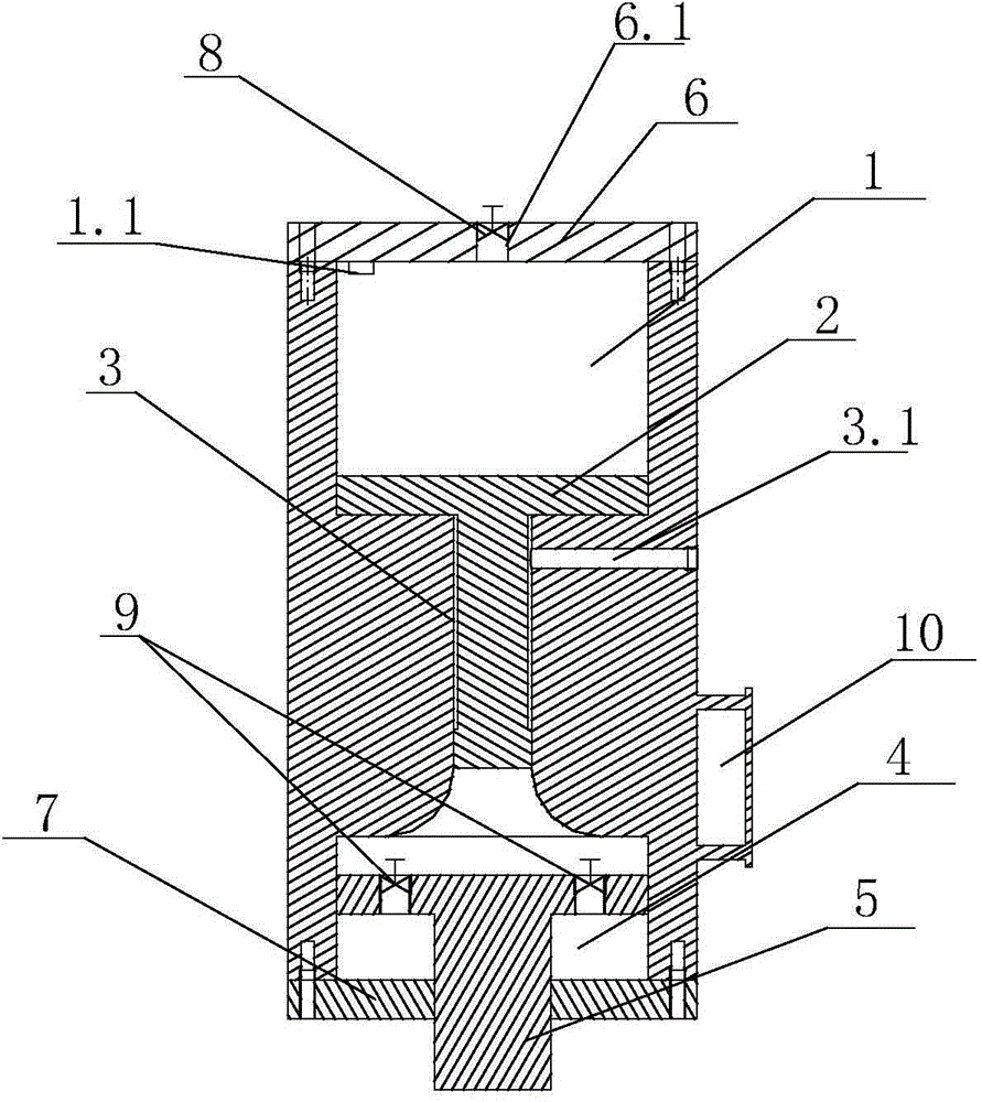
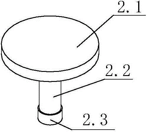
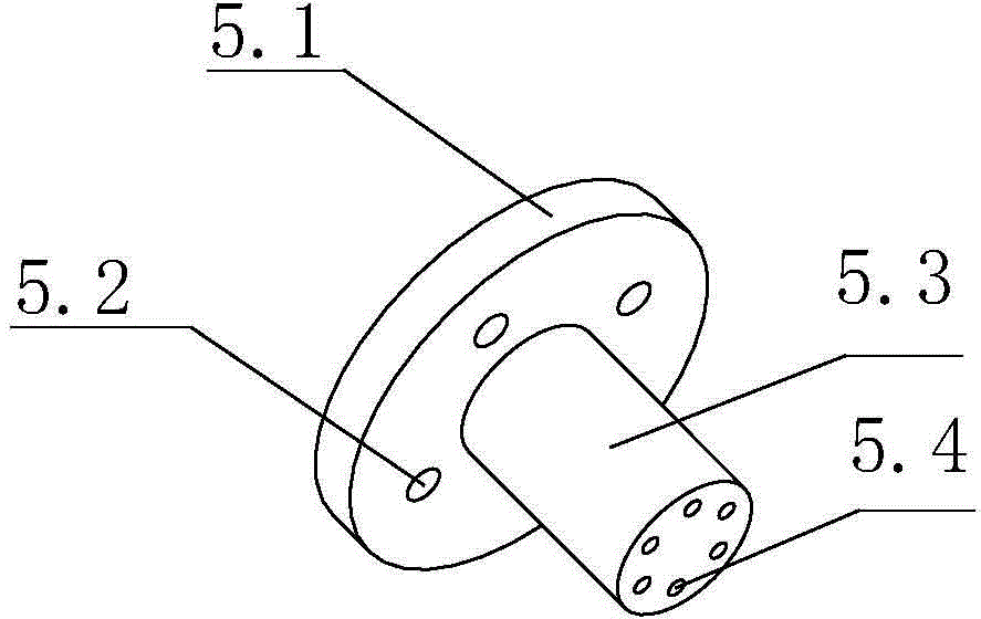
[0021] Such as Figure 1 to Figure 3 As shown, a gas-liquid coupling shock isolation device of the present invention includes a pneumatic cylinder 1 and a hydraulic cylinder 4, and the pneumatic cylinder 1 and hydraulic cylinder 4 are coaxially arranged. The cavity of the cylinder body of the pneumatic cylinder 1 communicates with the cavity of the cylinder body of the hydraulic oil cylinder 4 through the piston channel 3 .

[0022] The top of the cylinder chamber of the pneumatic cylinder 1 is sealed by the upper cylinder cover 6, and the upper cylinder cover 6 is threadedly connected with the isolated device 11. The top of the cylinder chamber of the pneumatic cylinder 1 is respectively provided with a pressure sensor 1.1 and an exhaust hole 6.1 communicating with the atmosphere, and an exhaust solenoid valve 8 is arranged in the e...


PUM


Abstract

The invention discloses a gas-liquid coupling type impact isolating device. The gas-liquid coupling type impact isolating device comprises a pneumatic air cylinder and a hydraulic oil cylinder which are coaxially arranged. A chamber of the pneumatic air cylinder is communicated with a chamber of the hydraulic oil cylinder through a piston channel. A pneumatic piston rod of the pneumatic air cylinder extends out of the bottom of the pneumatic air cylinder to be matched with the piston channel in a sealing and sliding mode, and the top of the pneumatic air cylinder is connected with an isolated device. A hydraulic piston rod of the hydraulic oil cylinder extends out of the bottom of the hydraulic oil cylinder to be connected with a foundation of a ship. The hydraulic piston of the hydraulic oil cylinder is provided with an oil discharging through hole in the axial direction, and the oil discharging through hole is internally provided with an oil discharging solenoid valve. The top of the chamber of the pneumatic air cylinder is respectively provided with a pressure sensor and an exhaust vent communicated with the atmosphere, and the exhaust vent is internally provided with an exhaust solenoid valve. The exhaust solenoid valve and the oil discharging solenoid valve are controlled by a control circuit to be started or stopped. By means of the gas-liquid coupling type impact isolating device, the impact energy can be dissipated fast, the impact load transmitted to the device from the foundation of the ship can be greatly reduced, and the impact resisting capability of the device is improved.

Description

technical field [0001] The invention relates to the field of impact isolation of ship power equipment, in particular to a gas-liquid coupling type impact isolation device. Background technique [0002] With the development of modern military technology, the impact equivalent and impact duration of weapon explosions have increased significantly, and the threat to military ship equipment has become more serious. In this context, the anti-shock technology requirements of modern military ships are constantly improving, and the anti-shock devices in harsher use environments are putting forward higher requirements. [0003] The traditional shock isolation design is to store the sharp energy of the transient and strong shock wave in the shock isolator in the form of potential energy to the maximum extent, so that the isolator will be greatly deformed, and then, according to the characteristics of the isolation system itself Slowly release the energy in the isolator according to th...

Claims


Application Information

Patent Timeline
Patent Type & Authority Patents(China)
IPC IPC(8): F16F9/06F16F9/32F16F9/36
Inventor 张春辉赵建华汪玉杜俭业王俊炎孙宇鹏张瑞波
Owner NAVAL UNIV OF ENG PLA
Learn More