Steam soot blower of novel multifunctional blowing tube

A soot blowing tube, multi-functional technology, applied in the direction of combustion product treatment, combustion method, solid residue removal, etc., can solve the problems of easy dead angle, poor soot blowing effect, poor soot blowing fullness, etc. Injection efficiency, improvement of soot blowing effect, effect of increasing soot blowing area

Active Publication Date: 2014-04-16
WUHAN SANYU MACHINE CO LTD
View PDF5 Cites 3 Cited by
  • Summary
  • Abstract
  • Description
  • Claims
  • Application Information

AI Technical Summary

Problems solved by technology

[0002] The existing telescopic steam soot blower can only expand and contract in a single axis direction, the fullness of the soot blowing is poor, dead angles are prone to appear in the soot blowing process, and the soot blowing efficiency is low; in addition, the existing steam soot blower can only provide Single-fluid jet soot blowing cannot meet the needs of different working conditions, and the soot blowing effect is not good; and the existing steam soot blower sprays steam at the same pressure and flow rate during the entire rotation process, which cannot achieve High-pressure and high-intensity spraying in places with serious dust accumulation, low-pressure and low-intensity spraying in places with light dust accumulation

Method used


Image

  • Steam soot blower of novel multifunctional blowing tube
  • Steam soot blower of novel multifunctional blowing tube

Examples


Embodiment Construction

[0025] The present invention will be further described in detail below in conjunction with the accompanying drawings, so that those skilled in the art can implement it with reference to the description.

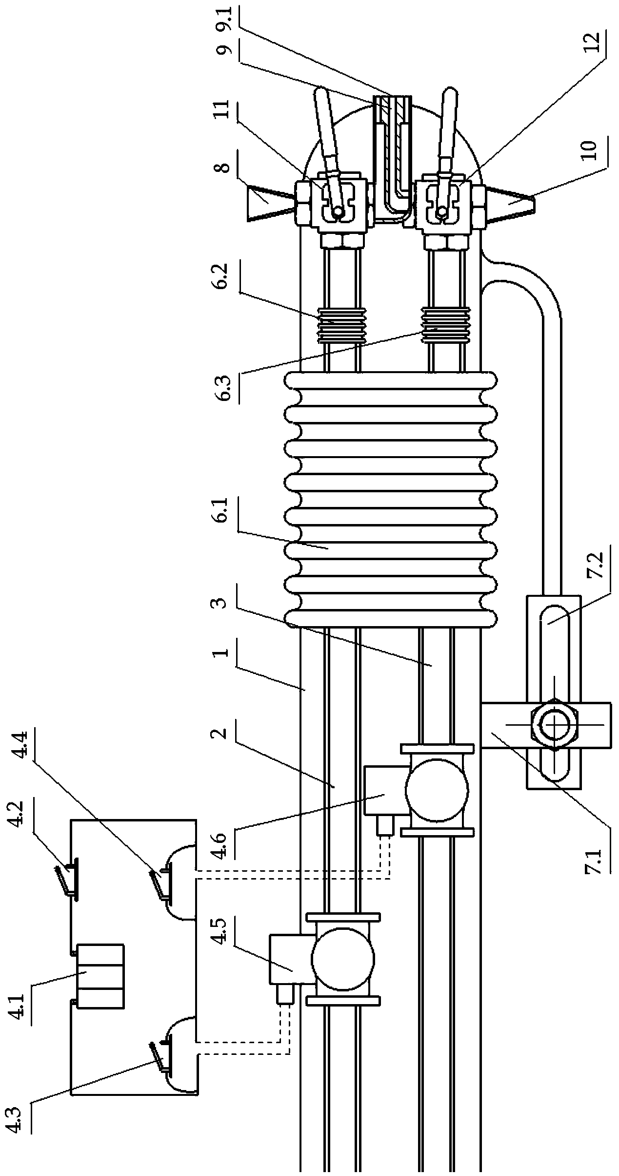
[0026] The present invention provides a steam soot blower of a novel multifunctional soot blowing tube, comprising:

[0027] The soot blowing pipe 1 is wrapped with two parallel conveying pipes: the steam conveying pipe 2 and the high-temperature water conveying pipe 3, the steam conveying pipe is used for conveying steam, and the high-temperature water conveying pipe is used for conveying high-temperature water,

[0028] The fluid switch control unit 4 includes a power supply 4.1, a steam switch solenoid valve 4.5, a high temperature water switch solenoid valve 4.6, a switch 1 (4.2), a switch 2 (4.3) and a switch 3 (4.4). On the pipe, the high-temperature water switch solenoid valve is installed on the high-temperature water delivery pipe, and the power supply, switch 1, swi...


PUM


Abstract

The invention relates to a steam soot blower, in particular to a steam soot blower of a novel multifunctional blowing tube. The steam soot blower of the novel multifunctional blowing tube is characterized in that the steam soot blower of the novel multifunctional blowing tube comprises the blowing tube, a fluid switch control unit, an angle adjusting device and a blowing tube nozzle assembly. Two parallel conveying tubes are wrapped by the blowing tube, wherein the two parallel conveying tubes are a steam conveying tube and a high-temperature water conveying tube. The fluid switch control unit comprises a power source, a steam switch solenoid valve, a high-temperature water switch solenoid valve, a first switch, a second switch and a third switch. The angle adjusting device comprises a metal bellows assembly and an adjusting support assembly, wherein the metal bellows assembly comprises a metal bellows I mounted on the blowing tube, a metal bellows II mounted on the steam conveying tube and a metal bellows III mounted on the high-temperature water conveying tube, and the adjusting support comprises a fixed assembly and an adjusting assembly. The blowing tube nozzle assembly comprises a steam blowing tube nozzle, a combined blowing tube nozzle and a high-temperature water blowing tube nozzle, and the blowing tube assembly is connected with the steam conveying tube and the high-temperature water conveying tube through a tee joint ball valve. According to the steam soot blower of the novel multifunctional blowing tube, multiple blowing modes and multiple blowing angles can be obtained, the blowing area can be enlarged, high blowing full scale can be achieved, no blowing dead angles can be left, effective spraying can be improved, and the blowing effect is improved.

Description

technical field [0001] The invention relates to the field of steam soot blowing, in particular to a steam soot blower of a novel multifunctional soot blowing tube. Background technique [0002] The existing telescopic steam soot blower can only expand and contract in a single axis direction, the soot blowing fullness is poor, dead angles are prone to appear during the soot blowing process, and the soot blowing efficiency is low; in addition, the existing steam soot blower can only provide Single fluid jet soot blowing cannot meet the needs of different working conditions, and the soot blowing effect is not good; and the existing steam soot blower sprays steam at the same pressure and flow rate during the whole rotation process, which cannot achieve High-pressure, high-intensity jetting where dust accumulation is severe, and low-pressure, low-intensity jetting where dust accumulation is relatively light. Contents of the invention [0003] Aiming at the above-mentioned tech...

Claims


Application Information

Patent Timeline
Patent Type & Authority Applications(China)
IPC IPC(8): F23J1/00F23J3/00
Inventor 卢璐娇
Owner WUHAN SANYU MACHINE CO LTD
Why Eureka
Try Eureka