
High-velocity motion object pose vision measurement method based on structured light
A high-speed motion and visual measurement technology, which is applied in the directions of measuring devices, photogrammetry/video metrology, surveying and navigation, etc.
- Summary
- Abstract
- Description
- Claims
- Application Information
AI Technical Summary
Problems solved by technology
Method used
Image

Examples
Embodiment Construction
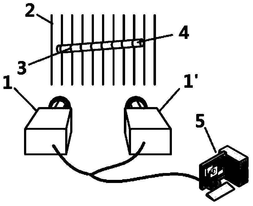
[0043] The specific embodiments of the present invention will be described in detail below in conjunction with the technical solutions and accompanying drawings. attached figure 1 It is a schematic diagram of the pose measurement method for high-speed moving objects based on structured light strips. This method adopts two left and right high-speed cameras 1, 1' to collect the images of the measured cylinder 4 and the vertical laser stripes 2, transmit the collected images to the graphics workstation 5, and utilize the laser stripes generated by the measured cylinder 4 The distance constraint from the deformation part 3 to the axis is optimized to obtain the target axis, and finally the position and attitude information of the target is obtained.
[0044] First install the measuring device, fix the left and right high-speed cameras 1, 1', adjust the focal length so that the common field of view of the focal plane 600mm away from the camera is 1m×1m. Laser stripes 2 are projec...
PUM
 Abstract
Description
Claims
Application Information