
Multifunctional material electromagnetic parameter test system and method

A technology for electromagnetic parameters and testing systems, applied in the fields of analyzing materials, measuring magnetic properties, using wave/particle radiation for material analysis, etc. Improve test efficiency, improve test foundation, and simplify the effect of operation

Active Publication Date: 2014-04-16
刘宝帅
View PDF5 Cites 13 Cited by
  • Summary
  • Abstract
  • Description
  • Claims
  • Application Information

AI Technical Summary

Problems solved by technology

With the improvement of electronic equipment requirements, higher requirements are put forward for the testing of electromagnetic parameters of materials, and the testing of many parameters needs to be completed by different systems. Although the tested materials have not changed, the errors of different systems and The influencing factors of the test are all different, so the overall evaluation of the multifunctional material will be biased by different parameters tested by different systems, which will affect the objective evaluation of the entire material

Method used


Image

  • Multifunctional material electromagnetic parameter test system and method
  • Multifunctional material electromagnetic parameter test system and method
  • Multifunctional material electromagnetic parameter test system and method

Examples


Embodiment Construction

[0035] The present invention will be further described in detail below in conjunction with specific embodiments, which are explanations of the present invention rather than limitations.

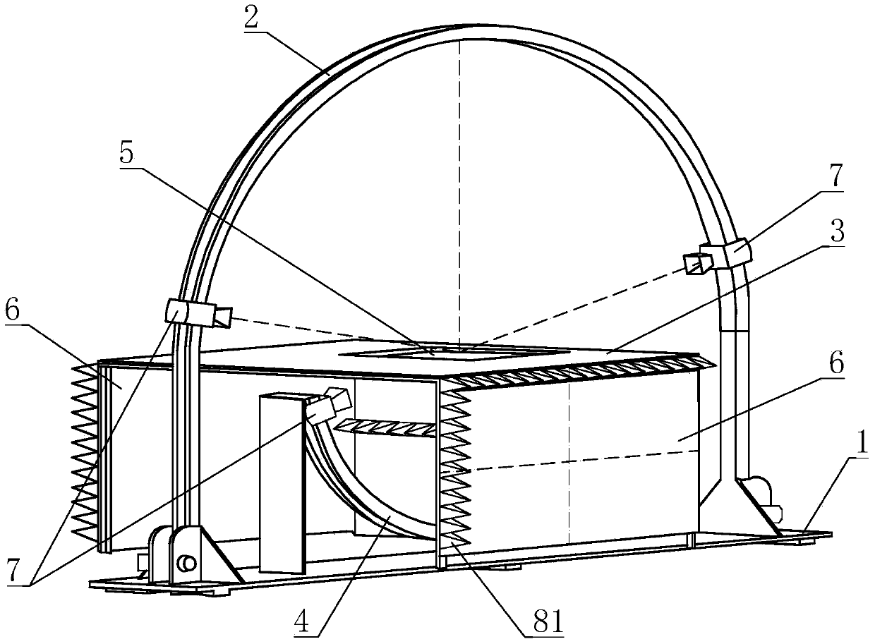
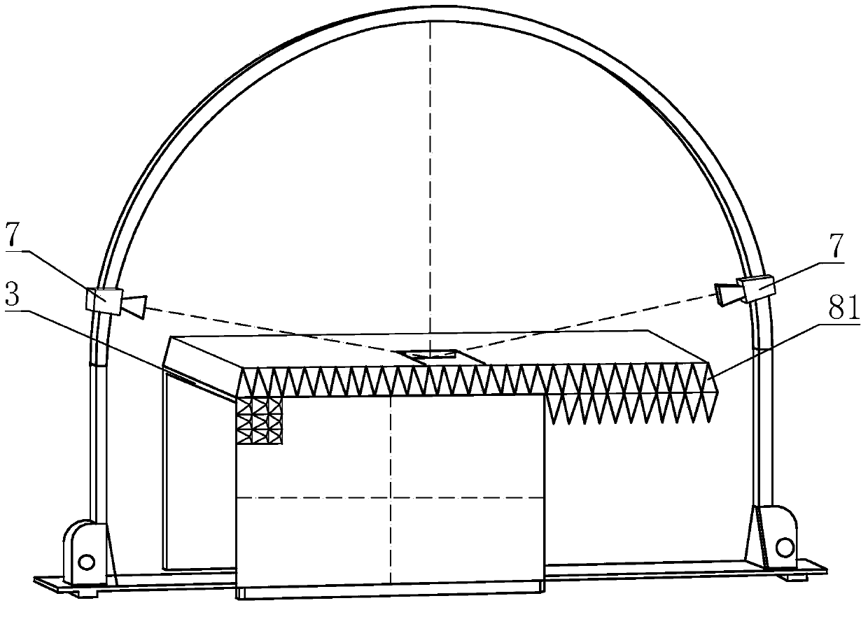
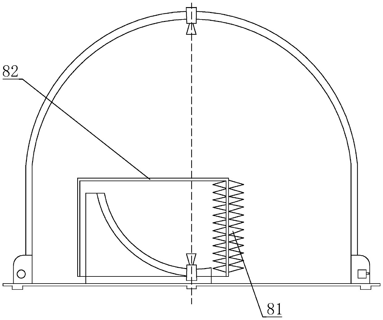
[0036] The multifunctional material electromagnetic parameter testing system of the present invention, such as figure 1 As shown, it includes a base 1, and an arched frame 2 respectively fixed on the base 1, a workbench 3 and an auxiliary slide rail 4; In the plane, the center of the circle coincides with the center of the arc of the arch frame 2; the workbench 3 is provided with a transmission hole 5, and the center point of the transmission hole 5 coincides with the center of the auxiliary slide rail 4; thereby realizing three-center coincidence, This enables the test system to meet its most basic test requirements during adjustment, simplifies the operation, and improves the test accuracy; the workbench 3 is set horizontally and is fixedly connected to the base through the vertical plates ...


PUM


Abstract

The invention discloses a multifunctional material electromagnetic parameter test system. The multifunctional material electromagnetic parameter test system comprises a base, an arched frame, an operating platform and an auxiliary sliding rail, wherein the arched frame, the operating platform and the auxiliary sliding rail are respectively fixed on the base; the auxiliary sliding rail is of a circular arc shape, the auxiliary sliding rail and the arched frame are positioned in the same plane, and the center of the auxiliary sliding rail and the center of an arc part of the arched frame are coincided; the operating platform is provided with a transmission hole, and the center point of the transmission hole and the center of the auxiliary sliding rail are coincided; the operating platform is horizontally arranged and is fixedly connected with the vase through vertical plates arranged on the two sides of the operating platform; each of the arched frame and the auxiliary sliding rail is provided with a signal antenna which is connected in a sliding manner, and the signal antennae are used for emitting or receiving the signals. In a multifunctional material electromagnetic parameter test method based on the test system, the relative positions of the arched frame and the auxiliary sliding rail is regulated according to different test parameters; due to the arrangement of the operating platform and the installation of a standard metal plate or a test material on the vertical plates, emitted signals and received signals of the signal antennae are utilized to obtain the test parameters; in addition, electromagnetic parameters for testing a testing material include a transmissivity / or reflectivity and / or space electromagnetic parameter.

Description

technical field [0001] The invention relates to the field of microwave testing, in particular to a multifunctional material electromagnetic parameter testing system and testing method. Background technique [0002] Microwave dielectric materials are widely used in various communication and radar systems. The dielectric parameters (or complex dielectric constant) of dielectric materials are the basic and important parameters for designing microwave circuits and systems. With the improvement of electronic equipment requirements, higher requirements are put forward for the testing of electromagnetic parameters of materials, and the testing of many parameters needs to be completed by different systems. Although the tested materials have not changed, the errors of different systems and The influencing factors of the test are all different, so the overall evaluation of the multi-functional material through the different parameters of the non-same system test will lead to deviation...

Claims


Application Information

Patent Timeline
IPC IPC(8): G01N23/00G01R27/26G01R33/12
Inventor 盛雄
Owner 刘宝帅
Learn More