
Semiconductor device and manufacturing method thereof

A semiconductor and device technology, applied in the field of semiconductor devices and their preparation, can solve the problems of easy generation of bubbles and voids, difficulty in filling dielectrics, and difficulty in controlling the height of fins, and achieves easy filling, high electron mobility and driving current. Better than the filling effect

Active Publication Date: 2014-04-16
SEMICON MFG INT (SHANGHAI) CORP
View PDF5 Cites 2 Cited by
  • Summary
  • Abstract
  • Description
  • Claims
  • Application Information

AI Technical Summary

Problems solved by technology

[0004] The side walls of the currently prepared fins are generally vertical, and there are also fins with inclined side walls or bowl-shaped (bowing profile) in the prior art, such as Figure 10 As shown, the etching process during the preparation of the fin is divided into two steps. First, the groove is etched to form the upper part of the fin, and then the groove is further etched to obtain the lower part of the fin, and then the dielectric is filled. etching and other steps, and then form the fin structure, but in this process the height of the upper part of the fin is not easy to control
[0005] At present, in the manufacturing process of FinFET, the height of the fins is not easy to control, and the side walls of the fins are mostly vertical structures, and after the fins are formed, the CD of the grooves between the fins is very small and the The sidewall of the fin is vertical, which makes it difficult to fill the dielectric, and it is easy to generate air bubbles and voids. Therefore, the current method needs to be improved to make the height of the fin easier to control, and the filling effect in the subsequent process is better. it is good

Method used


Image

  • Semiconductor device and manufacturing method thereof
  • Semiconductor device and manufacturing method thereof
  • Semiconductor device and manufacturing method thereof

Examples


Embodiment Construction

[0044] In the following description, numerous specific details are given in order to provide a more thorough understanding of the present invention. It will be apparent, however, to one skilled in the art that the present invention may be practiced without one or more of these details. In other examples, some technical features known in the art are not described in order to avoid confusion with the present invention.

[0045] For a thorough understanding of the present invention, a detailed description will be presented in the following description to illustrate the semiconductor device and the method of manufacturing the same according to the present invention. Obviously, the practice of the invention is not limited to specific details familiar to those skilled in the semiconductor arts. Preferred embodiments of the present invention are described in detail below, however, the present invention may have other embodiments besides these detailed descriptions.

[0046] It shou...


PUM

PropertyMeasurementUnit
angleaaaaaaaaaa
angleaaaaaaaaaa
thicknessaaaaaaaaaa

Abstract

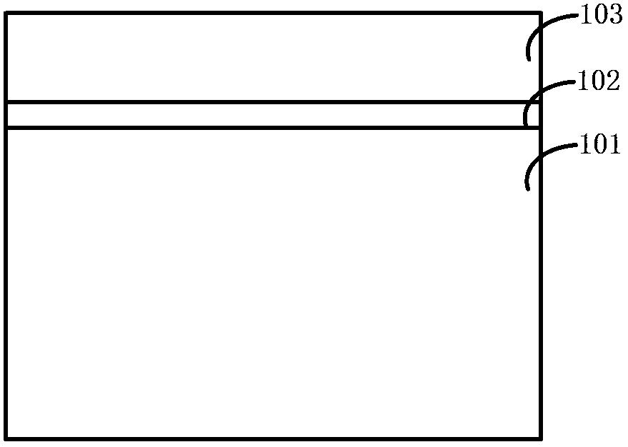
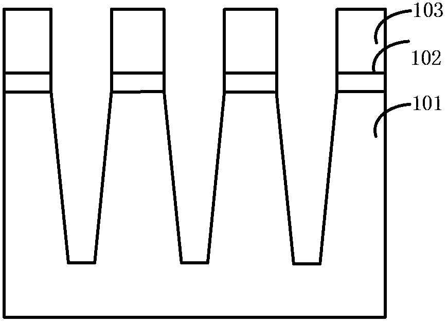
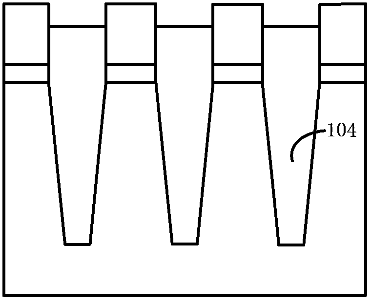
The invention relates to a semiconductor device and a manufacturing method of the semiconductor device. The method includes the steps that a semiconductor substrate is provided, and a hard mask layer is formed on the substrate; the hard mask layer is patterned to form an opening; the semiconductor substrate is etched, and conical trenches and fins located between the trenches are formed in the substrate; the conical trenches are filled with dielectric materials and flattened; part of the dielectric materials are removed through etching, and therefore the dielectric materials are made to be higher than the upper surface of the substrate; the hard mask layer is etched back to increase the critical size of the opening; part of the dielectric materials are removed through etching to make the fins exposed; the fins are etched to be divided into two sections with different inclination degrees, upper side walls and lower side walls which are different in inclination degrees are formed, and meanwhile a part of the hard mask layer is removed. The semiconductor device manufactured through the method comprises the fins with the dual inclined side walls, the heights of the fins are easier to control, and performance of the device is more stable.

Description

technical field [0001] The invention relates to the field of semiconductors, in particular, the invention relates to a semiconductor device and a preparation method thereof. Background technique [0002] The improvement of integrated circuit performance is mainly achieved by continuously shrinking the size of integrated circuit devices to increase its speed. Currently, as the semiconductor industry has progressed to nanotechnology process nodes in pursuit of high device density, high performance, and low cost, especially when semiconductor device dimensions drop to 22nm or below, challenges from manufacturing and design have led to three-dimensional design Such as the development of Fin Field Effect Transistor (FinFET). [0003] Compared with the existing planar transistors, the FinFET device has more superior performance in terms of channel control and reducing shallow channel effects; the planar gate structure is arranged above the channel, and the gate in the FinFET The...

Claims


Application Information

Patent Timeline
Patent Type & Authority Applications(China)
IPC IPC(8): H01L21/336H01L29/78H01L29/06
CPCH01L29/66818H01L29/7853H01L21/823431H01L29/66795
Inventor 张海洋王新鹏
Owner SEMICON MFG INT (SHANGHAI) CORP
Learn More