Charging method, assembly and terminal

A charging module and terminal technology, applied in the field of electronics, can solve the problems of increasing terminal heat dissipation cost and hardware loss, increasing production cost, heat dissipation difficulty, etc., and achieving the effect of improving heat dissipation efficiency and charging efficiency

Inactive Publication Date: 2014-04-16
SHENZHEN GIONEE COMM EQUIP
View PDF5 Cites 23 Cited by
  • Summary
  • Abstract
  • Description
  • Claims
  • Application Information

AI Technical Summary

Problems solved by technology

However, the use of a charging chip with a larger output current will cause the problem of increased production costs due to the price of the charging chip, and the greater the output current, the higher the heat generation of the charging chip, which will not only bring difficulty in heat dissipation, but also It will increase the heat dissipation cost and hardware loss of the terminal

Method used


Image

  • Charging method, assembly and terminal
  • Charging method, assembly and terminal
  • Charging method, assembly and terminal

Examples


Embodiment Construction

[0032] The following will clearly and completely describe the technical solutions in the embodiments of the present invention with reference to the accompanying drawings in the embodiments of the present invention. Obviously, the described embodiments are some of the embodiments of the present invention, but not all of them. Based on the embodiments of the present invention, all other embodiments obtained by persons of ordinary skill in the art without creative efforts fall within the protection scope of the present invention.

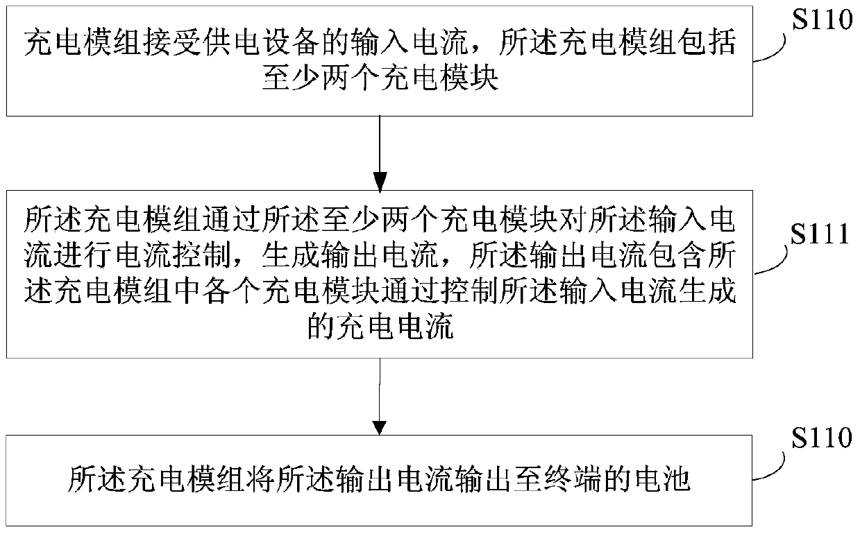
[0033] An embodiment of the present invention provides a charging method, which may include: a charging module accepts an input current from a power supply device, the charging module includes at least two charging modules; the charging module passes through the at least two charging modules Perform current control on the input current to generate an output current, the output current includes the charging current generated by each charging module in th...


PUM


Abstract

The embodiment of the invention provides a charging method, assembly and terminal. The method comprises the steps that a charging module assembly receives an input current of a power supply device, wherein the charging module assembly comprises at least two charging modules; the charging module assembly controls the input current through the charging modules to generate an output current, wherein the output current comprises charging currents generated when the charging modules of the charging module assembly control the input current; the charging module assembly outputs the output current to a battery of the terminal. According to the charging method, assembly and terminal, heat dissipation efficiency and charging efficiency can be improved.

Description

technical field [0001] The present invention relates to the field of electronic technology, in particular to a charging method, component and terminal. Background technique [0002] At present, the utilization rate of smart terminals with touch screens is very high, and their own processors and display screens consume a lot of power during work. In order to better serve users, manufacturers also increase the battery capacity of terminals to the original capacity. At the same time, it brings the problem of longer charging time and affects the use of users. For this reason, in the prior art, a charging chip that can be used for high-current output is built into the terminal, and the battery of the terminal is charged by the current output by the charging chip, which can improve the charging efficiency under ideal conditions. [0003] In the hardware device of the existing technical solution, the terminal battery only receives power from the charging chip for high current outp...

Claims


Application Information

Patent Timeline
Patent Type & Authority Applications(China)
IPC IPC(8): H02J7/00H01M10/44
CPCY02E70/40Y02E60/10
Inventor 江克俊
Owner SHENZHEN GIONEE COMM EQUIP
Why Eureka
Try Eureka