Device and method for geometric correction of detector of cone-beam CT (computed tomography) system

A correction device and geometric correction technology, applied in the field of biomedical imaging, can solve problems such as inapplicability, and achieve the effect of simple and fast operation, fast and effective geometric correction

Active Publication Date: 2014-04-23
PEKING UNIV
View PDF7 Cites 15 Cited by
  • Summary
  • Abstract
  • Description
  • Claims
  • Application Information

AI Technical Summary

Problems solved by technology

This method makes too many assumptions in the formula derivation process, such as the detector has no in-plane rotation, no out-

Method used


Image

  • Device and method for geometric correction of detector of cone-beam CT (computed tomography) system
  • Device and method for geometric correction of detector of cone-beam CT (computed tomography) system
  • Device and method for geometric correction of detector of cone-beam CT (computed tomography) system

Examples


Embodiment Construction

[0036] The present invention will be further described through the embodiments below in conjunction with the accompanying drawings.

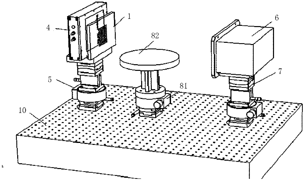
[0037] Such as figure 1 As shown, the cone beam CT system detector geometric correction device of this embodiment includes: a correction plate 1, a detector 4, an adjustment table 5, an X-ray source device 6 and an X-ray source table 7; wherein, the detection surface of the detector 4 Vertical to the bottom surface; the adjustment table 5 includes an adjustment device and a horizontal table mounted on the adjustment device; the X-ray source table 7 and the adjustment table 5 are located at both ends respectively, and the bottom surface of the detector 4 is placed on the horizontal table top of the adjustment table 5 , the correction plate 1 is placed between the X-ray source device 6 and the detector 4 and placed on the table of the adjustment table 5 . The adjusting table 5 , the X-ray source table 7 and the rotating table are arranged on the ...


PUM


Abstract

The invention discloses a device and a method for geometric correction of a detector of a cone-beam CT (computed tomography) system. The correction device comprises a correction board, an adjusting board, the detector, an X-ray source device and an X-ray source table, wherein the X-ray source table and the adjusting board are arranged at two ends of the correction device respectively, the X-ray source device is located on the X-ray source table, the bottom surface of the detector is placed on a horizontal table surface of the adjusting table, the correction board is arranged on the table surface of the adjusting table and positioned between the X-ray source device and the detector, a plurality of round through holes are formed in the correction board and form a through hole array, sizes of the through holes are the same, and the through holes are axially parallel. According to the device and the method for geometric correction of the detector of the cone-beam CT system, by means of the correction board with the through hole array, the detector of the cone-beam CT system can be subjected to convenient, fast, and effective geometric correction without calculation; by means of the correction board, the geometric position of the detector is firstly corrected, the position of a rotation table is subsequently corrected, and the operation is simple and fast.

Description

technical field [0001] The invention relates to the field of biomedical imaging, in particular to a correction device and a correction method for the geometric position of a cone-beam CT system detector. Background technique [0002] Computerized tomography (CT) plays a pivotal role in current nuclear medicine imaging, especially in the field of multimodal imaging. CT provides structural information and attenuation correction information for other modalities. It can be said that the reconstruction accuracy of CT determines the image reconstruction effect and image fusion effect of other modalities to a large extent. At present, 3D cone-beam CT generally adopts the FDK (Feldkamp) analytical reconstruction algorithm, but the 3D reconstruction effect of the FDK algorithm is very sensitive to the geometric parameters of the 3D cone-beam CT system, which requires that the relative geometric positions of the ray source, detector and rotating table be at In an ideal state, the cen...

Claims


Application Information

Patent Timeline
IPC IPC(8): A61B6/03G06T11/00
Inventor 任秋实周坤李真黄益星吕江超田涧姜喆杨昆
Owner PEKING UNIV
Why Eureka
Try Eureka