Electric heating type flow intelligent adjusting valve and control method thereof

An intelligent adjustment, electric heating technology, applied in valve details, valve devices, valve operation/release devices, etc., can solve the problems of high energy consumption, failure rate, high production cost, and large loss

Inactive Publication Date: 2014-04-23
KUNMING UNIV OF SCI & TECH
View PDF8 Cites 9 Cited by
  • Summary
  • Abstract
  • Description
  • Claims
  • Application Information

AI Technical Summary

Problems solved by technology

[0005] The invention provides an electrothermal flow intelligent regulating valve and its control method, which are used for regulating valves that have large loss, high e

Method used


Image

  • Electric heating type flow intelligent adjusting valve and control method thereof
  • Electric heating type flow intelligent adjusting valve and control method thereof
  • Electric heating type flow intelligent adjusting valve and control method thereof

Examples


Embodiment 1

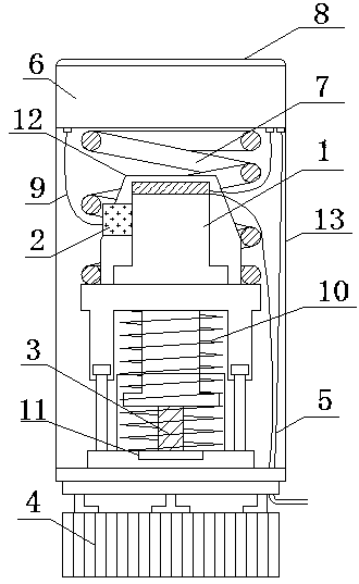
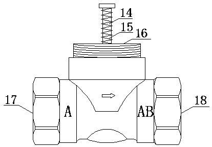
[0045] Embodiment 1: as Figure 1-4 As shown, an electrothermal flow intelligent regulating valve includes an electrothermal actuator, a control device and a valve. Force spring 10, moving plate 11, plastic shell 12, device shell 13, described control device comprises temperature sensor 2, control circuit 6, control panel 8, signal line 9, and described valve comprises valve stem 14, return spring 15, fixed Valve seat 16, inlet cavity 17, and outlet cavity 18; wherein the paraffin driver 1 is connected to the ejector rod 3 and placed inside the force transmission spring 10, the temperature sensor 2 fixed by the plastic shell 12 is close to the paraffin driver 1 and passed through the signal line 9 It is connected with the control circuit 6, and the control circuit 6 fixed by the device casing 13 is connected with the control panel 8 embedded in the surface of the device casing 13 by means of a plug and placed on the upper end of the position fixing spring 7, and the moving pie...

Embodiment 2

[0058] Embodiment 2: as Figure 1-4 As shown, an electrothermal flow intelligent regulating valve includes an electrothermal actuator, a control device and a valve. Force spring 10, moving plate 11, plastic shell 12, device shell 13, described control device comprises temperature sensor 2, control circuit 6, control panel 8, signal line 9, and described valve comprises valve stem 14, return spring 15, fixed Valve seat 16, inlet cavity 17, and outlet cavity 18; wherein the paraffin driver 1 is connected to the ejector rod 3 and placed inside the force transmission spring 10, the temperature sensor 2 fixed by the plastic shell 12 is close to the paraffin driver 1 and passed through the signal line 9 It is connected with the control circuit 6, and the control circuit 6 fixed by the device casing 13 is connected with the control panel 8 embedded in the surface of the device casing 13 by means of a plug and placed on the upper end of the position fixing spring 7, and the moving pie...

Embodiment 3

[0073] Embodiment 3: as Figure 1-4 as shown,

[0074] When the paraffin driver ejector rod stroke model is specifically used in the heating control process, the size of the experimental object (room) is selected to be 100cm×100cm×100cm, and according to the least square method curve fitting can be obtained m , n , The specific value of m =1; n =3; a 0 =0.2, a 1 =55.6; b 0 =-0.0002, b 0 =0.0013, b 2 =-0.0673, b 3 =6.8971.

[0075] An electrothermal flow intelligent regulating valve, including an electrothermal actuator, a control device and a valve, the electrothermal actuator includes a paraffin driver 1, a push rod 3, a fixing nut 4, a power cord 5, a position fixing spring 7, and a force transmission spring 10 , moving piece 11, plastic shell 12, device shell 13, described control device comprises temperature sensor 2, control circuit 6, control panel 8, signal line 9, and described valve comprises valve stem 14, return spring 15, fixed valve seat ...


PUM


Abstract

The invention relates to an electric heating type flow intelligent adjusting valve and a control method thereof and belongs to the field of automatic control technologies. The electric heating type flow intelligent adjusting valve comprises an electric heating actuator, a control device and a valve, wherein the electric heating actuator comprises a paraffin driver, an ejector rod, a fixed nut, a power supply wire, a position fixing spring, a force transmission spring, a moving sheet, a plastic shell and a device shell; the control device comprises a temperature sensor, a control circuit, a control panel and a signal wire; the valve comprises a valve rod, a returning spring, a fixed valve seat, an inlet cavity and an outlet cavity; the control method comprises the steps of detecting temperature of the paraffin driver through the temperature sensor, receiving a temperature signal through the control device and adjusting the temperature of the paraffin driver according to a travel model calculation and control strategy of the ejector rod of the paraffin driver so as to control the travel of the ejector rod and realize flow adjustment of a fluid medium. The electric heating type flow intelligent adjusting valve is compact in structure, long in service life, low in energy consumption, low in production cost and convenient to mount and maintain.

Description

technical field [0001] The invention relates to an electrothermal flow intelligent regulating valve and a control method thereof, belonging to the technical field of automatic control. Background technique [0002] Flow intelligent regulating valve is a flow regulating device widely used in the production of petrochemical, metallurgical and electric power industries to control the flow of fluid media. It is also widely used in the terminal temperature control of heating, air conditioning, refrigeration and other systems. [0003] The electric control valve commonly used in the prior art is mainly to use the electric motor to drive the valve to control the flow of the fluid medium in the industrial process. Its working principle is: the sensor converts the detected flow signal into a switch value or a standard analog control signal and feeds it back to the controller. Displacement to adjust the opening of the valve, thereby controlling the flow of the fluid medium. At prese...

Claims


Application Information

Patent Timeline
IPC IPC(8): F16K31/66
CPCF16K31/002
Inventor 杨承志张兴超孙浩刘贺
Owner KUNMING UNIV OF SCI & TECH
Why Eureka
Try Eureka