
A Cassegrain antenna detection system and its design method

A technology of Cassegrain antenna and detection system, applied in the field of millimeter wave and submillimeter wave antenna, can solve the problems of momentum imbalance, large size, inapplicability, etc., to reduce power consumption, power design and mechanical design convenience , the effect of high mechanical precision

Inactive Publication Date: 2015-09-23
BEIJING UNIV OF POSTS & TELECOMM
View PDF7 Cites 0 Cited by
  • Summary
  • Abstract
  • Description
  • Claims
  • Application Information

AI Technical Summary

Problems solved by technology

It is a relatively big challenge to achieve the mechanical precision of the sub-mirror in the rotating state
In addition, the size of the sub-mirror of the Cassegrain antenna is still relatively large, and the momentum imbalance may still exist
[0005] It can be seen that most of the current shaped surface algorithms are not suitable for solving the problems caused by purely mechanical control scanning
However, the algorithm for shaping the sub-mirror surface of the Cassegrain antenna still has not completely solved the problems caused by purely mechanical control scanning, and even brought new problems

Method used


Image

  • A Cassegrain antenna detection system and its design method
  • A Cassegrain antenna detection system and its design method
  • A Cassegrain antenna detection system and its design method

Examples


Embodiment Construction

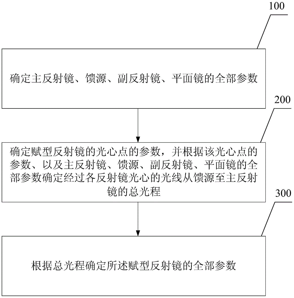
[0033] In order to make the object, technical solution and advantages of the present invention clearer, the present invention will be further described in detail below with reference to the accompanying drawings and examples.

[0034] The present invention provides a Cassegrain antenna detection system, such as figure 1 As shown, the antenna detection system includes: a main reflector 20 with an opening 21 in the center, a feed source 10 and a secondary reflector 30 respectively located on both sides of the mirror surface of the main reflector 20, and a feed source 10 located on the main reflector 20 Shaped mirror 40 and plane mirror 50 on the same side.

[0035] The light emitted by the feed source 10 is reflected by the shaped reflector 40 and the plane mirror 50 in sequence, passes through the opening 21 of the main reflector 20 , is reflected by the secondary reflector 30 and the main reflector 20 , and exits.

[0036] The center of the shaped reflector 40 is located on t...


PUM


Abstract

The invention provides a Cassegrain antenna detection system and a design method thereof. The Cassegrain antenna detection system comprises a main reflector, a feed source, an auxiliary reflector, a shaping reflector and a plane mirror; and an opening hole is arranged at the center of the main reflector, the feed source and the auxiliary reflector are respectively arranged at the two sides of the main reflector, and the shaping reflector and the plane mirror, together with the feed source, are arranged at the same side of the main reflector. The light emitted by the feed source is successively reflected by the shaping reflector and the plane mirror, passes through the opening hole of the main reflector, and then is reflected by the auxiliary reflector and the main reflector and is sent out. The shaping reflector and the plane mirror can rotate simultaneously around the central shaft of the main reflector so as to change the emitting field. According to the system and the design method thereof, when the shaping reflector with the small size and the plane mirror with the small size are rotated in an integrated mode around the symmetrical shaft of the main reflector, the emitting direction rotates in an integrated mode around the symmetrical shaft of the main reflector, thereby achieving an objective of scanning and substantially reducing the non-conservation phenomenon of the momentum during the rotation process.

Description

technical field [0001] The invention relates to the field of millimeter wave and submillimeter wave antennas, in particular to a Cassegrain antenna detection system and a design method thereof. Background technique [0002] At present, millimeter wave and submillimeter wave antennas are widely used in the fields of earth exploration, atmospheric remote sensing, maritime satellites and radio astronomy. A large number of radiation systems are used in millimeter wave and submillimeter wave detection systems in various fields, and one of the key subsystems in these radiation systems is the antenna system. In order to realize high-gain, narrow-beam antennas, large-size reflector antennas are usually used. Traditional mirror antennas mainly include parabolic antennas and Cassegrain antennas. The outgoing direction of these conventional mirror antennas is determined. Therefore, for some detection systems that require scanning, this is usually achieved by mechanically controlling...

Claims


Application Information

Patent Timeline
Patent Type & Authority Patents(China)
IPC IPC(8): H01Q3/20H01Q19/18H01Q19/185H01Q19/19
Inventor 刘小明俞俊生陈晓东
Owner BEIJING UNIV OF POSTS & TELECOMM
Learn More