
Public transformer cabinet

A technology of public transformer boxes and cabinets, which is applied in the substation/power distribution device shell, substation/switch layout details, electrical components, etc., and can solve problems such as loose locking of box doors and brackets, potential safety hazards, and electric leakage. To achieve the effect of avoiding large-scale leakage, avoiding damage, and avoiding leakage

Inactive Publication Date: 2014-04-23
XIANGSHAN YISHAN IND DESIGN
View PDF7 Cites 2 Cited by
  • Summary
  • Abstract
  • Description
  • Claims
  • Application Information

AI Technical Summary

Problems solved by technology

However, due to the over-standardization of public transformer cabinets, the details are often easily overlooked, and there have been no changes and developments for decades
Its disadvantages are as follows: firstly, due to the simple structure of the threading hole, electricians have to bend the end of the wire to feed the wire when threading the wire, which is very troublesome, and in most cases, the construction of the public transformer box is mostly The cable is very difficult; and when the cable diameter is too large, the cable protective layer is damaged due to the cutting force of the threading hole, resulting in leakage; in the rainy season, raindrops will flow in from the threading hole, resulting in large-scale leakage , bringing safety hazards to construction workers and passers-by
Secondly, because the box door and the bracket are in smooth contact, the box door and the bracket are not tightly locked and are easy to loosen; moreover, because the existing technology only considers the heat dissipation problem of the public transformer cabinet, but ignores the dustproof , resulting in a lot of dust and debris inside the public transformer cabinet, making it untidy

Method used


Image

  • Public transformer cabinet
  • Public transformer cabinet
  • Public transformer cabinet

Examples


Embodiment Construction

[0020] The present invention will be further described below in conjunction with the accompanying drawings and specific embodiments.

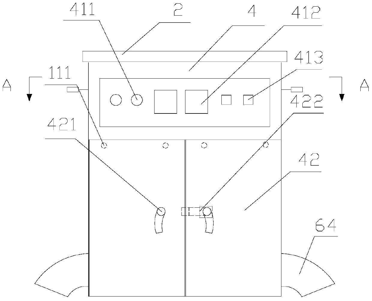
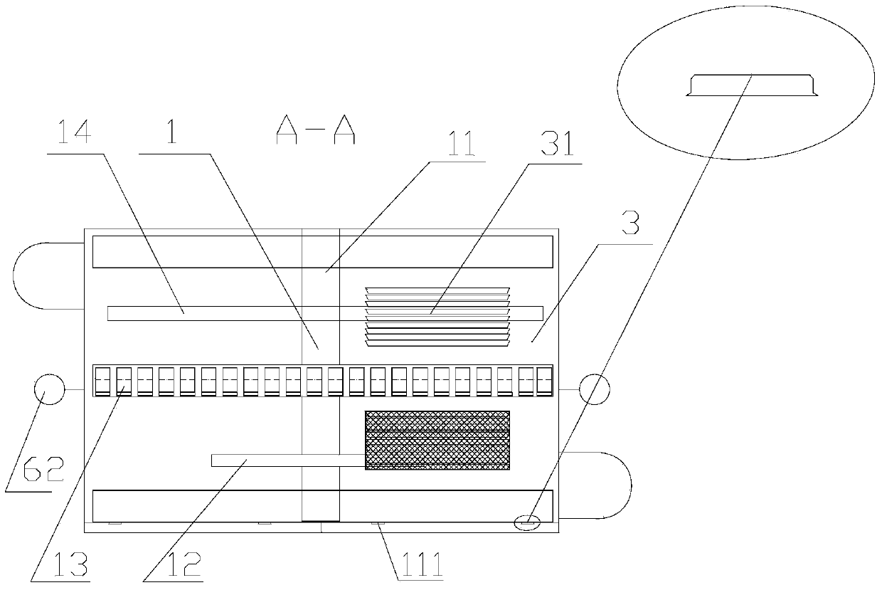
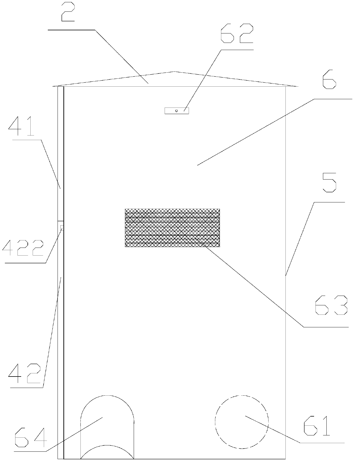
[0021] Such as figure 1 , figure 2 and image 3 As shown, scheme 1: a public transformer cabinet, including a public transformer cabinet body 1, a top cover 2 is provided on the top of the public transformer cabinet body 1, a bottom plate 3 with a first cooling groove 31 is provided at the bottom, and a front The upper part is provided with a front panel 41 with indicator light hole 411, instrument hole 412 and switch hole 413, the lower part is provided with a pair of cabinet doors 42 with door handle 421, and the back is provided with a fixed On the rear end panel 5 of the installation hole of the building, the left and right sides are respectively provided with a side panel 6 with a threading hole 61, a lifting lug 62 and a second cooling groove 63 for external tools to lift the public transformer cabinet; The top cover 2, the bottom pla...


PUM


Abstract

The invention relates to the public transformer field of a resident power supply protection type power distribution cabinet, in particular to a public transformer cabinet. The public transformer cabinet comprises a public transformer cabinet body, wherein the public transformer cabinet body (1) comprises a bracket (11); the bottom end of the public transformer cabinet body (1) is provided with a bottom plate (3) provided with a first cooling groove (31); the left side and the right side are respectively provided with a side panel (6) with a threading hole (61); and the front side is provided with one pair of cabinet body doors (42). The public transformer cabinet is characterized in that the threading holes (61) in the side panels (6) of the public transformer cabinet are provided with threading tube shields (64) of which the openings face downwards; the contact edge of the bracket (11) and the cabinet body doors (42) is provided with convex columns (111); the folding edges of the cabinet body doors (42) are provided with through holes; the convex columns (111) and the through holes are in interference fit; and the first cooling groove (31) and a second cooling groove (63) are provided with filter screens. According to the structure, the invention provides the public transformer cabinet which prevents electric leakage, rain and dust and causes the cabinet body doors to be more firmly locked.

Description

technical field [0001] The invention relates to the field of public transformers of protective power distribution cabinets for residents' power supply, in particular to a public transformer cabinet. Background technique [0002] There are two forms of power supply for residents today: one is called public transformer and the other is called special transformer. The so-called public transformer refers to the abbreviation for the local lines, transformers, and electric meters to each household that are all installed, maintained, and managed by the power supply bureau. The existing technology includes the main body of the public transformer box, which contains a bracket, the bottom of the public transformer box body is provided with a bottom plate with a first heat dissipation groove, and the left and right sides are respectively provided with threading holes for The lifting lugs and the side panel of the second heat sink that are lifted by external tools; there are a pair of ...

Claims


Application Information

Patent Timeline
IPC IPC(8): H02B1/46H02B1/28
Inventor 林明河黄仁如吴伟峰沈国鸿邬云霞徐剑中
Owner XIANGSHAN YISHAN IND DESIGN
Learn More