Laser projection equipment

A technology of laser projection and equipment, which is applied in the directions of optics, image reproducers using projection devices, instruments, etc., can solve the problems that cannot be fully received by the beam splitting module 16, the size is too large, and the miniaturization design of the laser projection equipment 10 is disadvantageous. Achieve the effect that is conducive to miniaturized design

Active Publication Date: 2014-04-23
QISDA OPTRONICS (SUZHOU) CO LTD +1
View PDF5 Cites 12 Cited by
  • Summary
  • Abstract
  • Description
  • Claims
  • Application Information

AI Technical Summary

Problems solved by technology

[0005] From the above, it can be seen that due to the limitation that the reflectors 18 must be arranged at intervals, the laser beam provided by the light combining module 12 will be too large to be completely received by the light splitting module 16. Therefore, the laser projection device 10 must Configure the light guide module 14 to reduce the laser beam to a size that can be completely received by the light splitting module 16
However, the configuration of the above-mentioned light guide module 14 will greatly increase the overall volume of the laser projection device 10, which is not conducive to the miniaturization design of the laser projection device 10

Method used


Image

  • Laser projection equipment
  • Laser projection equipment

Examples


Embodiment Construction

[0033] In order to have a further understanding of the purpose, structure, features, and functions of the present invention, the following detailed descriptions are provided in conjunction with the embodiments.

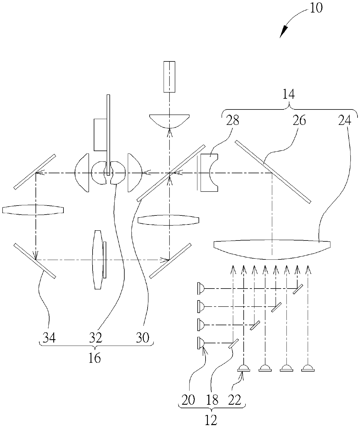
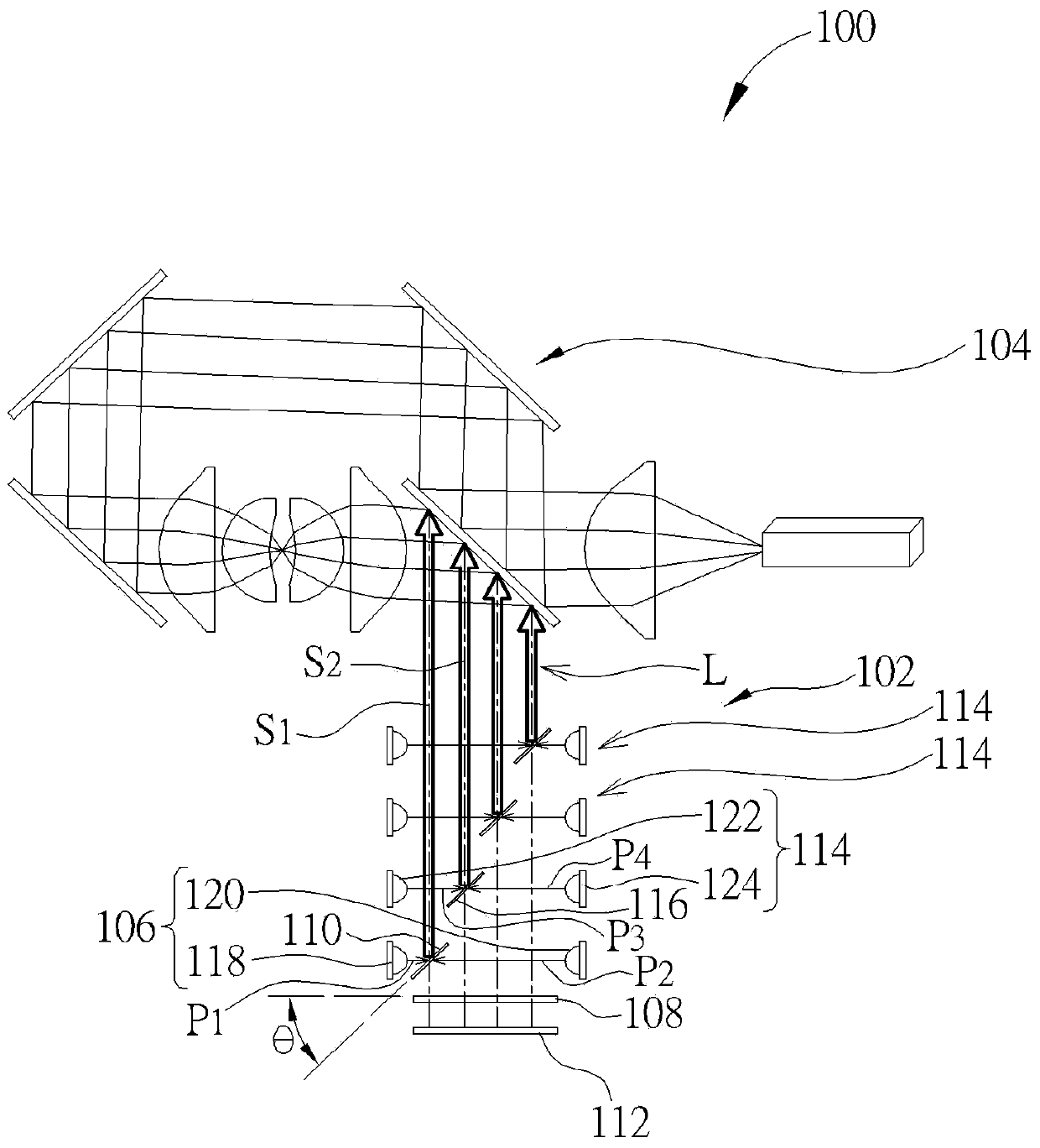
[0034] see figure 2 , which is a schematic diagram of a laser projection device 100 provided according to an embodiment of the present invention, as shown in figure 2 As shown, the laser projection device 100 includes a light combination module 102 and a light splitting module 104. Multiple imaging color lights (such as red light, blue light, and green light, etc.) required for subsequent projection imaging. The component configuration of the light-splitting module 104 can adopt a common light-splitting design in the prior art, such as figure 1 The configuration of the spectroscopic mirror, the fluorescent color wheel and the reflecting mirror in the spectroscopic module 16 will not be repeated here. The light combination module 102 includes a first laser light s...


PUM


Abstract

The invention provides laser projection equipment. The laser projection equipment comprises a light combination module and a light splitting module, wherein the light combination module comprises a first laser light source group, a quarter-wave plate, a first spectroscope and a reflector; the first laser light source group comprises a first laser light source and a second laser light source, which are oppositely arranged and are used for respectively transmitting first polarized light and second polarized light with the same polarization; the first spectroscope is inclined to the quarter-wave plate for reflecting the second polarized light to penetrate the quarter-wave plate and reflecting the first polarized light; the reflector is parallel to the quarter-wave plate and is adjacent to the first laser light source group for reflecting the second polarized light to the quarter-wave plate so as to cause the second polarized light to penetrate through the first spectroscope and to be combined with the first polarized light to form laser beam after penetrating through the quarter-wave plate. The light splitting module is used for receiving the laser beam so as to split the laser beam into a plurality of imaging colored light.

Description

technical field [0001] The present invention relates to a laser projection device, especially a laser projection module that uses a beam splitter, a quarter-wave plate and a reflector to combine polarized light to directly reduce the size of the laser beam generated by the light combination module. Background technique [0002] Generally speaking, common laser projection equipment adopts the configuration of light combining module and light splitting module to generate multiple imaging color lights for subsequent projection and imaging. For the relevant configuration, please refer to figure 1 . figure 1 It is a schematic diagram of a laser projection device 10 in the prior art. Such as figure 1 As shown, the laser projection device 10 includes a light combining module 12, a light guide module 14, and a light splitting module 16, wherein the light combining module 12 includes a plurality of mirrors 18, a plurality of first laser light sources 20, and a plurality of second l...

Claims


Application Information

Patent Timeline
Patent Type & Authority Applications(China)
IPC IPC(8): H04N9/31G03B21/20
Inventor 王凯俊
Owner QISDA OPTRONICS (SUZHOU) CO LTD
Why Eureka
Try Eureka