
Novel piezoelectric valveless micromixer

A micro-mixer and piezoelectric technology, applied in the field of micro-mechanics, can solve the problems of high energy consumption, low liquid flow rate and Reynolds number, large ratio of fluid surface area to volume, etc., achieving low power consumption, simple structure, The effect of simple flow resistance

Inactive Publication Date: 2014-04-30
JIANGSU UNIV
View PDF5 Cites 7 Cited by
  • Summary
  • Abstract
  • Description
  • Claims
  • Application Information

AI Technical Summary

Problems solved by technology

Among them, the micro-mixer has many defects: due to the reduction of the scale, the ratio of the fluid surface area to the volume in the micro-channel is quite large, the flow rate and Reynolds number of the liquid are low, and it is often in a state of laminar flow, and the mixing is often molecular. Diffusion motion in the horizontal, making mixing of minute liquids difficult
[0003] The Chinese patent publication number is: CN 102145265 A, the application number is: 201110091097.8, and the name is: a piezoelectric microfluidic mixer, its structure is relatively complicated, and the mixing effect of the main structure telsa valve is not good, and its diffusion tube will produce Negative pressure, large flow resistance, more energy consumed during pumping

Method used


Image

  • Novel piezoelectric valveless micromixer
  • Novel piezoelectric valveless micromixer
  • Novel piezoelectric valveless micromixer

Examples


Embodiment Construction

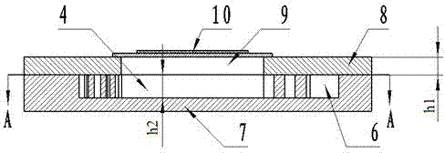
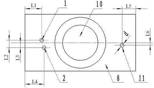
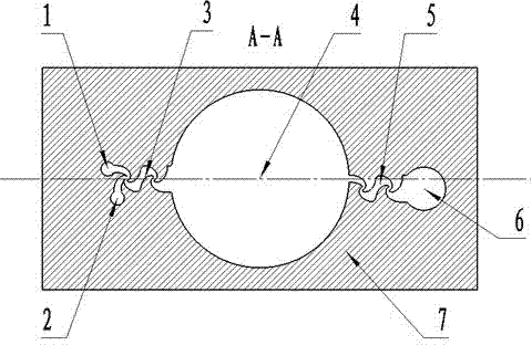
[0014] Such as Figure 1~3 As shown, the present invention includes pump inlet one 1, pump inlet two 2, inlet mixing unit 3, pump body pump chamber 4, outlet mixing unit 5, outlet buffer chamber 6, pump body 7, upper base body 8, base body pump chamber 9, The piezoelectric vibrator 10 and the pump outlet 11. The pump body 7 and the upper base body 8 are bonded together up and down. The upper base body 8 is provided with a pump inlet 1, a pump inlet 2, a pump outlet 11 and a base pump chamber 9. The pump body 7 is provided with a pump inlet mixing unit 3 , pump body pump chamber 4, outlet mixing unit 5, outlet buffer chamber 6. The piezoelectric vibrator 10 is made by bonding piezoelectric ceramics to an elastic substrate, and is fixed directly above the pump cavity 9 of the substrate by an adhesive. On the upper substrate 8, the pump inlet 1 and the pump inlet 2 communicate with the inlet mixing unit 3, the inlet mixing unit 3 communicates with the pump cavity 4, the pump ca...


PUM


Abstract

The invention discloses a novel piezoelectric valveless micromixer, which comprises a pump body and an upper matrix fixed above the pump body. A piezoelectric vibrator is fixed right above a matrix pump cavity; the pump body is provided with a pump inlet mixing unit, a pump body cavity, an outlet mixing unit and an outlet buffer cavity; a pump inlet one and a pump inlet two are communicated with the inlet mixing unit; the inlet mixing unit is communicated with the pump body cavity; the pump body cavity is communicated with the outlet mixing unit; the outlet mixing unit is communicated with an outlet buffer cavity; the outlet buffer cavity is communicated with a pump outlet; the pump body cavity is communicated with the matrix cavity; the inlet mixing unit and the outlet mixing unit are both composed of (i) n ( / i) basic mixing units, which are connected smoothly end to end; and the contour of a horizontal axis section of a single basic mixing unit comprises four logarithmic spiral lines and straight lines, wherein the four logarithmic spiral lines have a same pole shank. The mixing unit comprising logarithmic spiral lines is merged into the piezoelectric pump as a system for conveying the mixed fluid, and has low power consumption and simple structure.

Description

technical field [0001] The invention relates to the micromechanical field of microfluid pumping and mixing, in particular to a novel piezoelectric valveless micromixer. Background technique [0002] The microfluidic system can realize the separation, sample addition, mixing, reaction, detection and other functions of the traditional biochemical detection process on the chip, which not only saves reagents, but also reduces risks (such as toxic or violently reactive reagents) . As an emerging technology, microchemical engineering can be used for analysis and comprehensive applications. The microreaction systems involved in microchemical engineering mainly include micromixers, microheat exchangers, and microchannels. Among them, the micro-mixer has many defects: due to the reduction of the scale, the ratio of the fluid surface area to the volume in the micro-channel is quite large, the flow rate and Reynolds number of the liquid are low, and it is often in a state of laminar ...

Claims


Application Information

Patent Timeline
Patent Type & Authority Applications(China)
IPC IPC(8): B01F13/00B01L3/00F04B43/04
Inventor 何秀华韦丹丹邓志丹杨嵩
Owner JIANGSU UNIV
Learn More