Auxiliary stripping mechanism in continuous die

A technology of in-mold and material removal, applied in the direction of launching equipment, etc., can solve problems such as hidden safety hazards, risk of mold explosion, poor stability of material removal structure, etc., and achieve the effect of reasonable design, safe continuous production and simple structure.

Inactive Publication Date: 2014-04-30
XIANGXIN AUTOMOTIVE COMPONENT TOOL & DIE
View PDF9 Cites 5 Cited by
  • Summary
  • Abstract
  • Description
  • Claims
  • Application Information

AI Technical Summary

Problems solved by technology

In addition, the parts 10 delivered later may sometimes run over the parts 8 to be stripped and fail to hit the parts 8 to be stripped and cause the parts 8 to be stripped to fall off. There is a risk of mold explosion
[0004] To sum up, the stripping structure in the traditional continuous mold has poor stability and cannot meet the needs of modern fast and efficient production. At the same time, there are certain safety hazards. The industry urgently needs a new type of auxiliary stripping mechanism in the continuous mold

Method used


Image

  • Auxiliary stripping mechanism in continuous die
  • Auxiliary stripping mechanism in continuous die

Examples


Embodiment

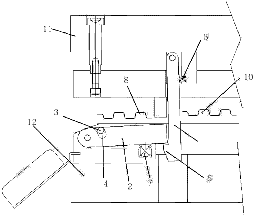
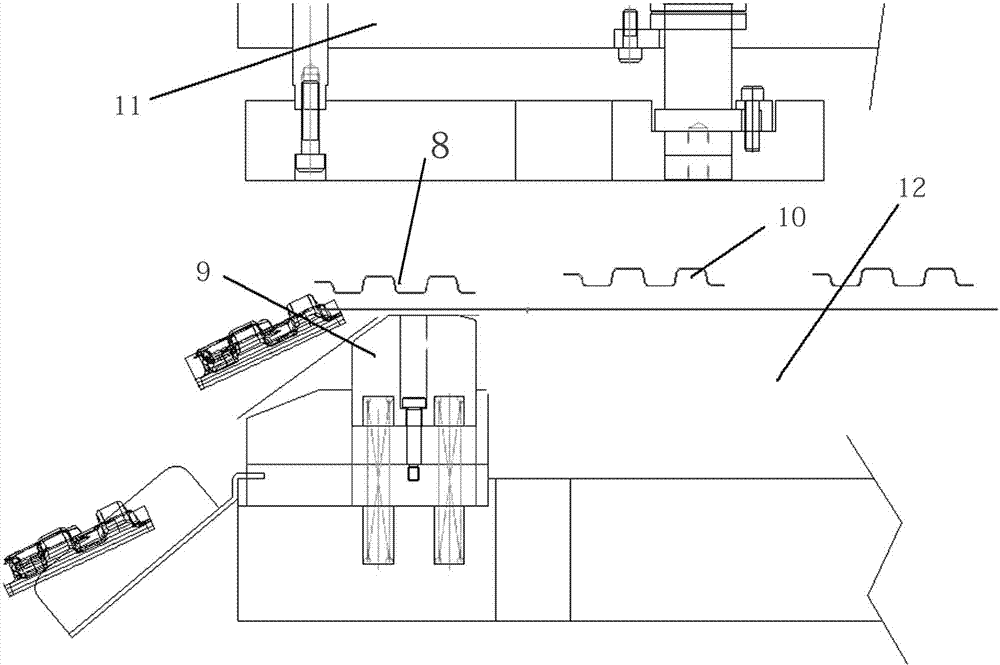
[0038] Such as figure 2 As shown, the present invention includes a swing rod 1, a stripping rod 2, and a limit post 3, and the upper end of the swing rod 1 is vertically installed in the upper template 11 of the continuous mold through a rotating shaft; the swing rod 1 is in the upper template 11 It can freely swing at an angle; the swing rod 11 is inserted into the lower template 12; the upper part of the swing rod 1 contacts and cooperates with a swing rod return spring 6 fixed in the upper template 11; the lower end of the swing rod 1 extends laterally A protrusion 5 with a straight side bevel forms a right-angle hook with the swing rod 1; the tail end of the stripping rod 2 is installed in the lower template 12 of the continuous mold through a rotating shaft, so that the stripping rod 2 is placed horizontally In the lower template 12; the other end of the stripping rod 2 can freely rotate upwards along the rotating shaft; the lower surface of the stripping rod 2 is in con...


PUM


Abstract

The invention discloses an auxiliary stripping mechanism in a continuous die. The mechanism comprises a swinging rod, a stripping rod and a limit column. The upper end of the swinging rod is vertically installed in an upper die plate of the continuous die through a rotating shaft, the swinging rod can swing freely with a certain angle in the upper die plate, and the swinging rod is inserted into a lower die plate. The upper portion of the swinging rod is in contact matching with a swinging rod resetting spring fixedly installed in the upper die plate, and a protrusion with a straight side and an inclined corner is transversely extended from the lower end of the swinging rod, and a right-angle hook is formed by the protrusion and the swinging rod. The tail end of the stripping rod is installed in the lower die plate of the continuous die through a rotating shaft to enable the stripping rod to be transversely arranged in the lower die plate. The swinging rod is matched with the stripping rod. The auxiliary stripping mechanism is simple in structure and reasonable in design, overcomes the shortcoming of a traditional stripping mechanism in the continuous die, and enables the continuous die to conduct efficient safe continuous production.

Description

technical field [0001] The invention relates to a mold, in particular to a mechanism with auxiliary continuous mold stripping. Background technique [0002] Continuous die refers to the cold stamping die that uses strip-shaped stamping raw materials in one stamping stroke, and uses several different stations on a pair of molds to complete multiple stamping processes at the same time. Move once with a fixed distance until the product is completed. In order to ensure the continuous processing of the continuous mold, the continuous mold needs to be stripped and sent out after the production is completed. [0003] The stripping structure used in the existing continuous die is relatively simple, such as figure 1 As shown, the existing continuous mold uses a liftable floating block 9 at the stripping port to lift the part 8, and the parts 10 delivered after use are pushed out to realize the stripping. This kind of stripping method has certain The deficiencies of concrete sa...

Claims


Application Information

Patent Timeline
Patent Type & Authority Applications(China)
IPC IPC(8): B21D45/04
Inventor 陈荣
Owner XIANGXIN AUTOMOTIVE COMPONENT TOOL & DIE
Why Eureka
Try Eureka