
Full-automatic workpiece assembling system

An assembly system, fully automatic technology, applied in the direction of metal processing, manufacturing tools, metal processing equipment, etc., can solve the problems of difficult assembly, large production space, lack of flexibility, etc., to ensure processing stability, improve production efficiency, and reasonable The effect of using space

Pending Publication Date: 2017-07-07
HUIZHOU ZHONGBANG ELECTRONICS
View PDF9 Cites 2 Cited by
  • Summary
  • Abstract
  • Description
  • Claims
  • Application Information

AI Technical Summary

Problems solved by technology

Due to the fragile pins of many electronic components, it is easy to damage the electronic components when the material tape is rolled up, so the material tape can only be arranged in a straight line, and it is unrealistic to use super long material tape in the production workshop, which takes up too much production space
The existing production method generally uses equidistant material belts, and when a material belt is produced, it is replaced manually. This production method has great potential safety hazards, and it is easy to cause damage to workers, and the production efficiency is low.
[0003] In particular, the existing assembly methods of power adapters mostly use manual assembly, which is difficult to assemble and has low efficiency. However, if mechanical assembly is used, due to the small size of some electronic components, pure mechanical assembly lacks flexibility.

Method used


Image

  • Full-automatic workpiece assembling system
  • Full-automatic workpiece assembling system
  • Full-automatic workpiece assembling system

Examples


Embodiment Construction

[0040] In order to facilitate those skilled in the art to understand, the present invention will be described in further detail below in conjunction with embodiment:

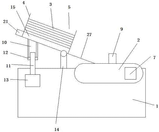
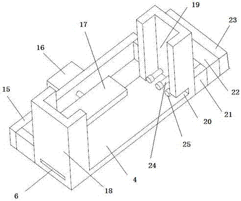
[0041] This embodiment provides a fully automatic workpiece assembly system, such as Figure 1-Figure 9As shown, it includes a feeding part and an assembly part arranged at the rear end of the feeding part. The feeding part includes a frame 1 and a feeding mechanism arranged at the front end of the frame 1 and a conveyor belt 2 arranged at the rear end of the frame 1. The feeding mechanism includes a storage strip 3 for accommodating the material tape, and the feeding mechanism also includes a material rack 4, and the material rack 4 is provided with a material cavity 5 for accommodating a plurality of storage strips 3, behind the material cavity 5 The end is provided with a discharge port 6 that allows the bottom material belt to pass through. The material rack 4 is placed obliquely backward and downward. As a...


PUM


Abstract

The invention discloses a full-automatic workpiece assembling system. The full-automatic workpiece assembling system comprises a feeding part and an assembling part arranged at the rear end of the feeding part. The feeding part comprises a rack, a feeding mechanism arranged at the front end of the rack, and a conveying belt arranged at the rear end of the rack, and the conveying belt is connected with a driving motor used for driving the conveying belt to operate. The assembling part comprises a case and a turntable rotatably arranged on the case. A stepping motor driving the turntable to rotate is arranged in the case. A plurality of mounting bases are annularly arranged on the turntable at equal angles. A nut feeding mechanism used for embedding nuts into the mounting bases, a taking mechanism used for taking material strips to the mounting bases, a safety braking mechanism used for embedding accessories into the mounting bases manually, a screw locking mechanism used for locking screws to corresponding positions, and a discharging mechanism used for discharging assembled pieces out of the mounting bases are arranged on the case around the turntable.

Description

technical field [0001] The invention relates to the field of power adapters, in particular to a fully automatic workpiece assembly system. Background technique [0002] Power adapter is a power supply conversion device for small portable electronic equipment and electronic appliances. It is generally composed of shells, transformers, inductors, capacitors, control ICs, PCB boards and other components. Its working principle is converted from AC input to DC output, widely used in various electronic devices. The market demand for power adapters is huge, so improving their production efficiency can effectively help companies occupy a larger market share, and how to quickly assemble a variety of electronic components for power adapters has great significance for their production efficiency. In the existing power adapter production line, in order to facilitate the assembly of electronic components, the same kind of electronic components are generally placed on the material tape, ...

Claims


Application Information

Patent Timeline
Patent Type & Authority Applications(China)
IPC IPC(8): B23P19/06
CPCB23P19/001B23P19/004B23P19/007B23P19/06
Inventor 梁德新向啟平
Owner HUIZHOU ZHONGBANG ELECTRONICS
Learn More