
Machining method of worm gear with straight profile helical surface

A processing method and technology of helical surface, applied in worm gears, belts/chains/gears, elements with teeth, etc., can solve the problems affecting popularization and application, the difficulty of precision plane worm gears, etc., and achieve high precision and simple processing methods. Effect

Active Publication Date: 2014-04-30
CHONGQING MACHINE TOOL GROUP
View PDF5 Cites 5 Cited by
  • Summary
  • Abstract
  • Description
  • Claims
  • Application Information

AI Technical Summary

Problems solved by technology

However, the tooth shape of the plane worm gear is a plane (straight plane or oblique plane) viewed from the cylindrical surface. With the current processing method, usually only single indexing can be used for milling, planing or grinding. To obtain precise The planar worm gear is very difficult, which greatly affects its popularization and application

Method used


Image

  • Machining method of worm gear with straight profile helical surface
  • Machining method of worm gear with straight profile helical surface
  • Machining method of worm gear with straight profile helical surface

Examples


Embodiment Construction

[0034] The present invention will be further described below in conjunction with the drawings and embodiments:

[0035] A method for processing straight-profile helical worm gears includes the following steps:

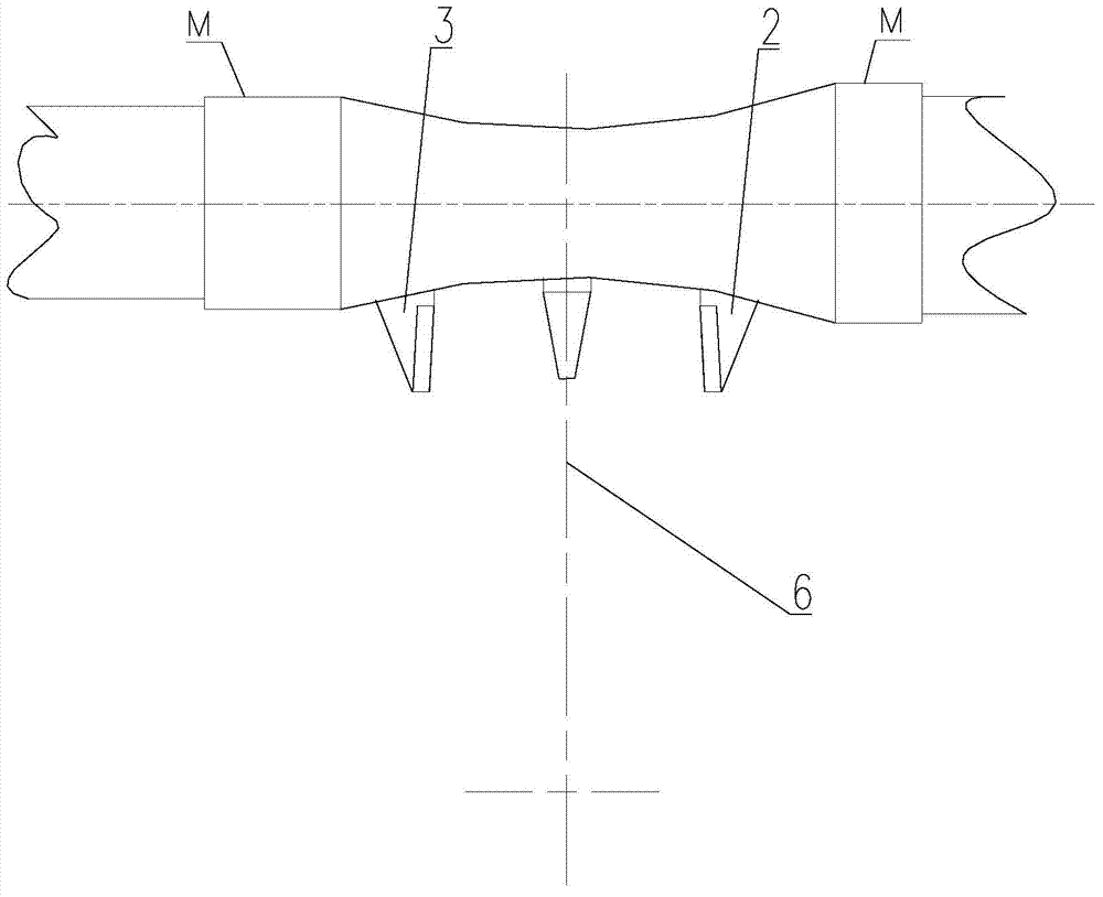
[0036] 1) Install the flying knife, such as figure 1 Shown:

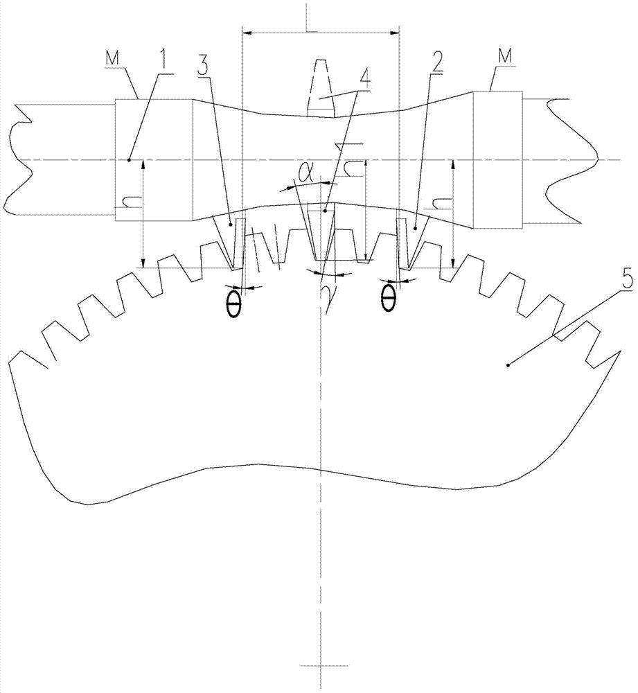
[0037] Fix the right-toothed flying knife 2 and the left-toothed flying knife 3 on the fly-knife arbor 1 with a screw interval; connect the fly-knife arbor 1 to the machine tool holder; among them, the inclination angle of the left and right-toothed flying knife , Tool nose distance L and tool extension length h are determined according to the following formula:

[0038] θ=α-180×n / z;

[0039] L=2×R f ×sin((n-0.5)×180 / z);

[0040] h=a-R f ×cos((n-0.5)×180 / z);

[0041] Among them, α is the tooth profile angle of the machined worm gear;

[0042] z is the number of teeth of the worm gear to be processed;

[0043] Rf is the diameter of the tooth root circle of the machined worm wheel;

[0044] n is the number of worm gear teet...


PUM


Abstract

The invention discloses a machining method of a worm gear with the straight profile helical surface. The machining method comprises step 1, installing a fly cutter, wherein a right tooth-shaped fly cutter and a left tooth-shaped fly cutter are separately fixed on a cutter rod of the fly cutter through screws and the cutter rod of the fly cutter is connected with a cutter frame of a machine tool; step 2, adjusting the machine tool, wherein the installation basic surface of the cutter rod is corrected with the working surface of the machine tool as the benchmark when the cutter rod with the installed cutter is arranged on the machine tool so as to enable the center line of the cutter rod of the fly cutter to be parallel to the working surface; step 3, performing cutter setting, wherein the cutting edges of the right tooth-shaped fly cutter and the left tooth-shaped fly cutter are symmetrical relative to the center line of a rotary working table; step 4, determining the spiral inclined angle of the worm gear, wherein the inclined angle of a grinding wheel, relative to the axis of the worm gear when a worm is ground, namely the inclined angle of the main plane, serves as the spiral angle of the machined worm gear and a differential hanging wheel of the machine tool is adjusted according to the inclined angle; step 5, performing feeding, wherein the feeding is performed to the total tooth depth in the radial direction and the axial feeding is performed to achieve the machining of the worm gear. According to the machining method of the worm gear with the straight profile helical surface, the machining method is simple and the accuracy of the worm gear is high.

Description

Technical field [0001] The invention relates to a processing method of a worm wheel. Background technique [0002] Worm gears and worm gears are a very widely used component in the machinery industry. According to their tooth profile, they can be divided into many types. Among them, the plane-enveloped toroidal worm pair has a large number of contact teeth, large load capacity, high transmission efficiency, and worm tooth profile. There is no need to modify the shape, and theoretically very high-precision worm gear pairs can be manufactured, which has attracted wide attention. However, the tooth profile of a plane worm gear is a flat plane (straight plane or oblique plane) viewed from the cylindrical surface. With the current processing methods, usually only a single index can be used for milling, planing or grinding. The plane worm gear is very difficult, which greatly affects its popularization and application. [0003] Therefore, those skilled in the art devote themselves to d...

Claims


Application Information

Patent Timeline
IPC IPC(8): B23F11/00
Inventor 谢小卿李先广廖承渝陈鹏梁博隆林
Owner CHONGQING MACHINE TOOL GROUP
Learn More