A locomotive traction braking method

A technology for locomotives and brake wedges, which is applied in the fields of locomotive traction and rail machinery transportation in mine level roads. It can solve problems such as sports car accidents, large cross-sections, and locking of braking devices, so as to prevent sports car accidents and reduce difficulty.

Inactive Publication Date: 2018-03-16
樊铁山
View PDF7 Cites 0 Cited by
  • Summary
  • Abstract
  • Description
  • Claims
  • Application Information

AI Technical Summary

Problems solved by technology

[0003] However, due to complex mine geological conditions, inaccurate design or multi-head construction, etc., the slope of the local transport line of the transport roadway is often > 10‰. However, the section of the modern mine transport roadway is large, and it is very difficult to modify and adjust the transport line
When a locomotive is used for traction in this transportation lane, since the locomotive head brake mainly relies on the brake device to brake the wheelset of the locomotive body, when the locomotive body pulls the train down through a local road section with a slope > 10‰, braking usually occurs. The moving device completely locks the wheelset of the main body of the locomotive, but there is still sliding between the wheelset and the track, which may easily cause a sports car accident or even cause casualties

Method used


Image

  • A locomotive traction braking method
  • A locomotive traction braking method
  • A locomotive traction braking method

Examples


Embodiment Construction

[0018] The structure of the present invention will be further described below in conjunction with the accompanying drawings.

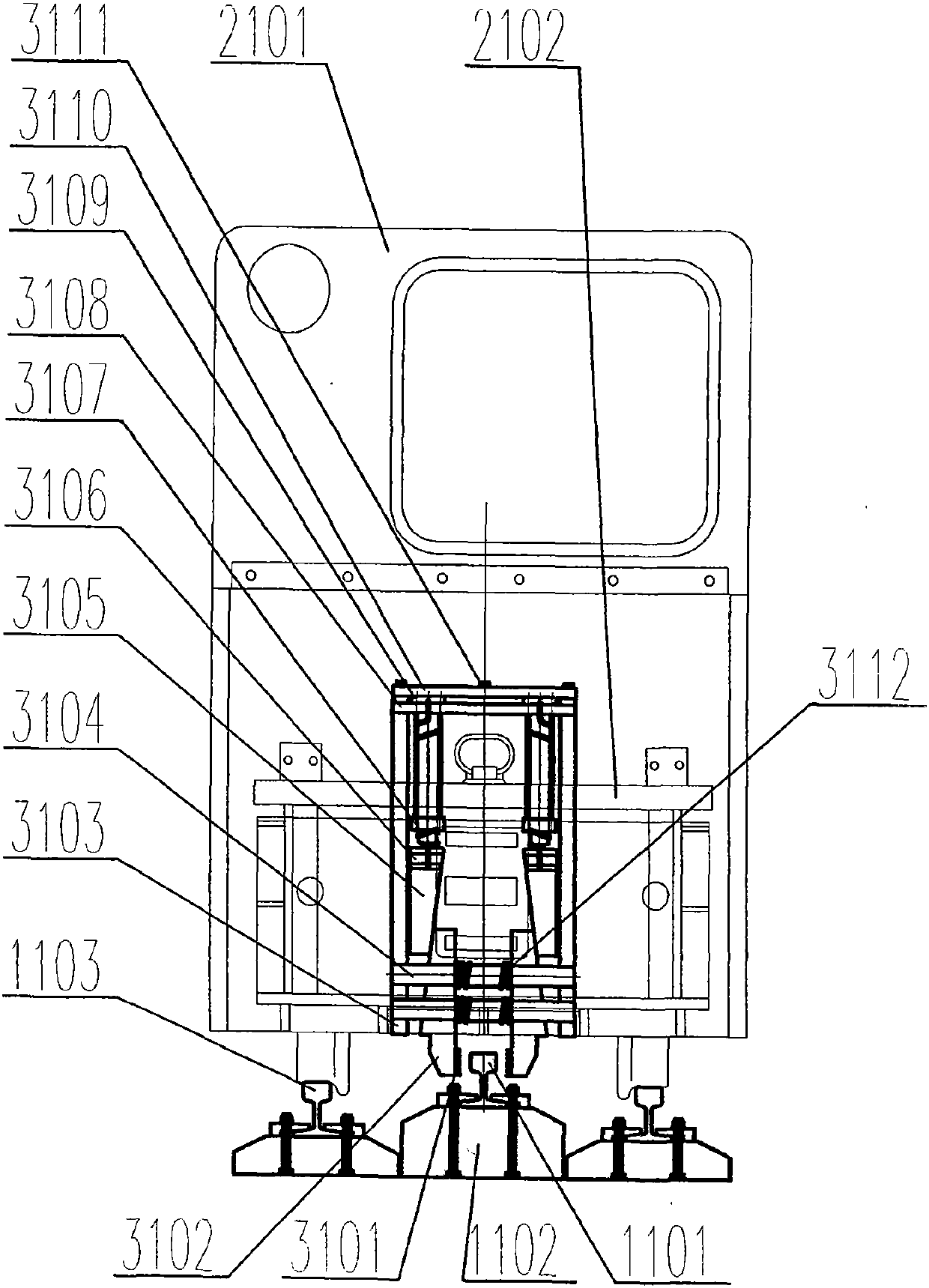
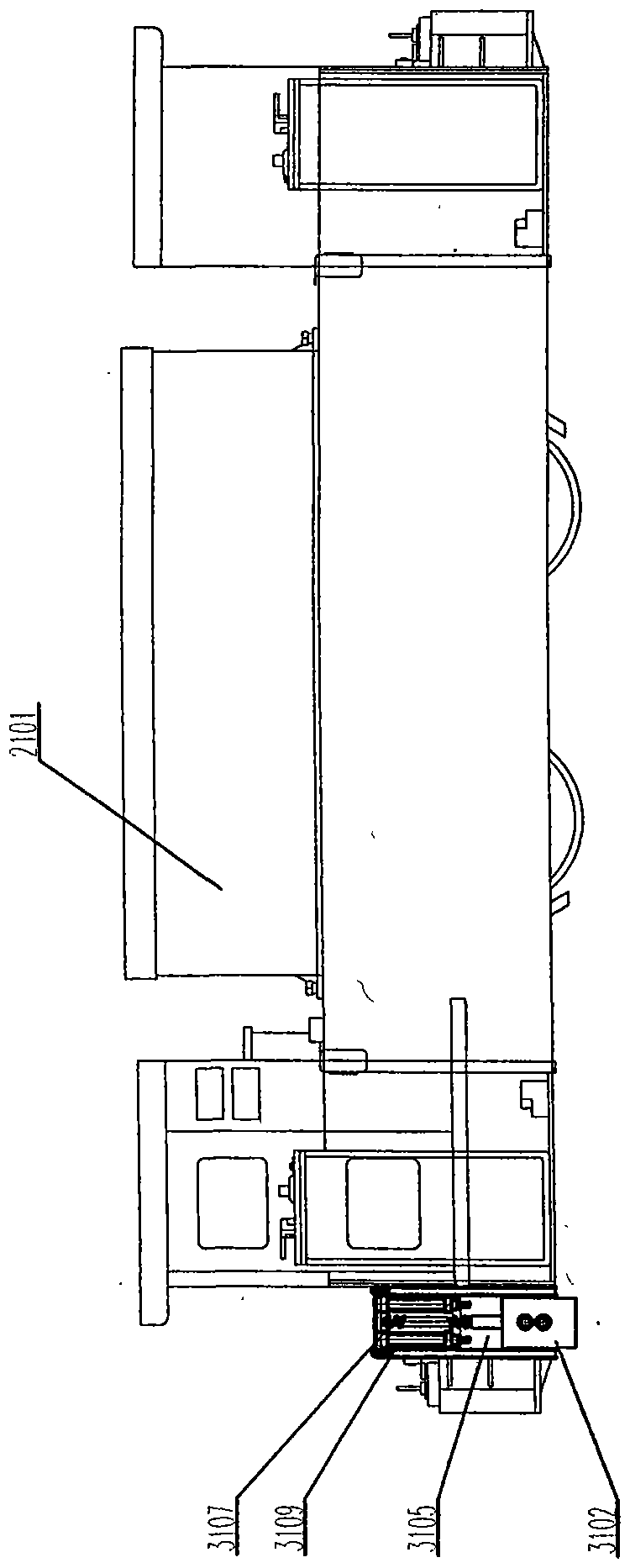
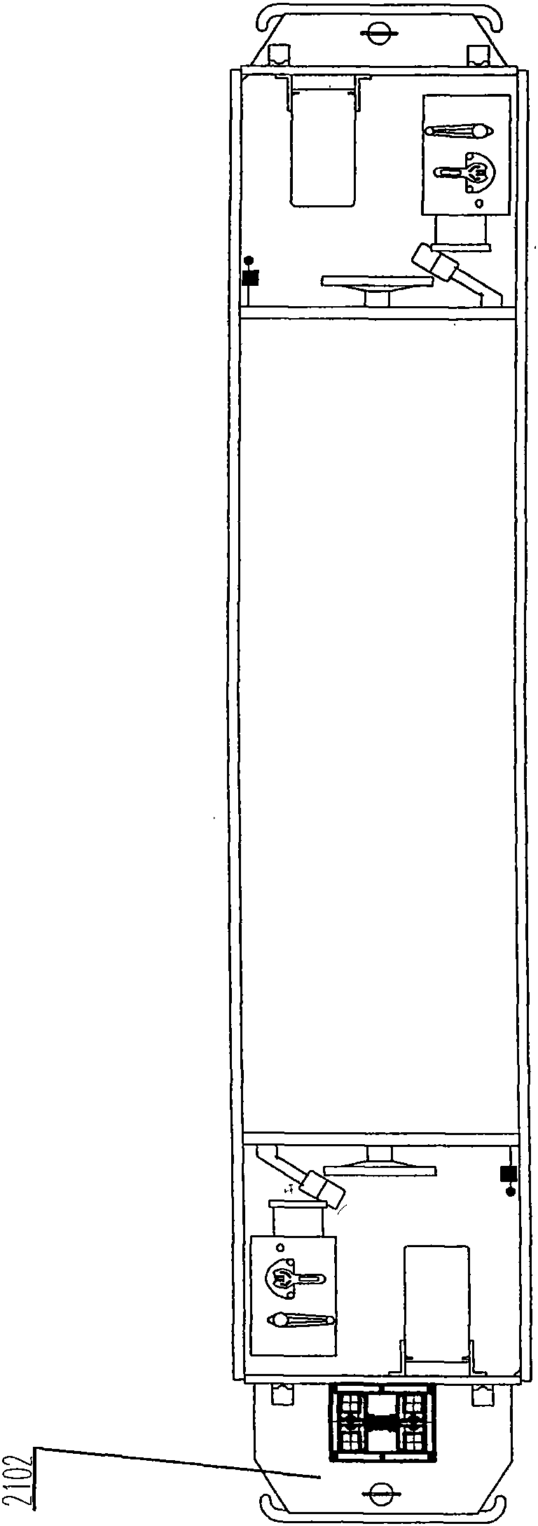
[0019] figure 1 , figure 2 , image 3 Middle: 1101. Brake track, 1102. Brake sleeper and pressing parts, 1103. Transportation road track, 2101. Locomotive body, 2102. Locomotive coupler meeting, 3101. Brake block, 3102. Brake wedge, 3103 .Brake box, 3104. Brake guide column, 3105. Booster wedge, 3106. Connecting pin, 3107. Return spring, 3108. Return spring fixing pin, 3109. Brake cylinder, 3110. Box cover , 3111. Bolt, 3112. Return spring.

[0020] Such as figure 1 , figure 2 , image 3 Shown, the technical scheme that the present invention takes:

[0021] The first step is to add a braking track 1101 on the track center line of the transportation road. The braking track 1101 is only laid on the straight line section of the transportation road track 1103, within the range of various turnouts and between various types of switches and the trans...


PUM


Abstract

The invention discloses a locomotive traction braking device, which belongs to the technical field of rail machinery transportation. The technical solution adopted is: the first step is to increase the laying of brake tracks on the center line of the track of the transport roadway. No brake track shall be laid within the range of 8m extending from the front and back of the straight line section of the track in the transportation avenue to the turnout; the second step is to install a friction brake box on the main body of the locomotive; the third step is to install a pneumatic brake box in the friction brake box. Type brake device and automatic reset mechanism, the pneumatic brake device cooperates with the brake track for friction braking; the automatic reset mechanism makes the pneumatic brake device in a non-braking state when the air is not continuously supplied; the fourth step, In the non-braking track section of the track, the pneumatic brake device is completely disengaged from the braking track. It changed the practice of relying solely on the traditional locomotive main body to brake its own wheelset, and added a friction braking device between the locomotive main body and the braking track to prevent sports car accidents.

Description

technical field [0001] The invention discloses a locomotive traction and braking method, which belongs to the technical field of rail machinery transportation, and in particular relates to the technical field of locomotive traction in mine level lanes. Background technique [0002] The slope of the transportation line of the underground transportation roadway of the mine is generally 3-10‰. If the slope is less than 3‰, it will be difficult to drain the roadway; if the slope is too large, it will be difficult for the electric locomotive to pull the train uphill, and it will be difficult to brake, which is unsafe, and the rim of the rail vehicle will be severely worn. The most ideal downhole line slope is equal resistance slope. The so-called equal resistance gradient is the line gradient when the downhill running resistance of the heavy train is equal to the uphill running resistance of the empty train. Because the running resistance of a heavy train is equal to that of an...

Claims


Application Information

Patent Timeline
Patent Type & Authority Patents(China)
IPC IPC(8): B61H7/12
Inventor 樊铁山樊孝师白如春李春苗邢俊峰徐春华樊晨斐樊泽阳白如镜徐宣真秦卫生雷恒太
Owner 樊铁山
Why Eureka
Try Eureka