
Inline capping machine

A capping machine, in-line technology, applied in the direction of conveyors, conveyor objects, bottles/container caps, etc., can solve the problems that the straw cannot be inserted into the bottle accurately, and the capping failure of the in-line capping machine, etc., to achieve structural The effect of simplicity, low cost, and high displacement accuracy

Active Publication Date: 2015-08-26
江苏汤姆森智能装备有限公司
View PDF7 Cites 0 Cited by
  • Summary
  • Abstract
  • Description
  • Claims
  • Application Information

AI Technical Summary

Problems solved by technology

[0003] For bottle caps with straws such as pump head caps, spray gun caps, spray caps, etc., since the straws of each cap are not necessarily vertically downward, some of them may be bent, so before screwing the cap, the bottle The straw of the cap may not be inserted into the bottle accurately, which eventually leads to the capping failure of the inline capping machine

Method used


Image

  • Inline capping machine
  • Inline capping machine
  • Inline capping machine

Examples


Embodiment 1)

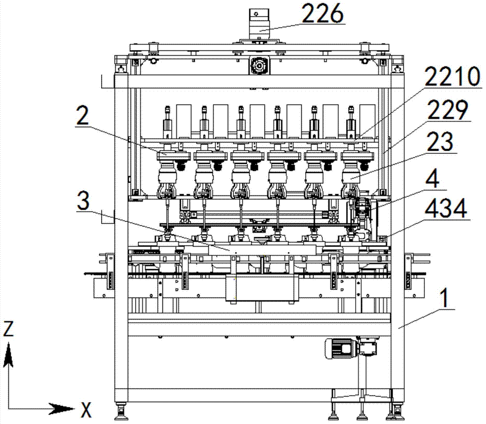
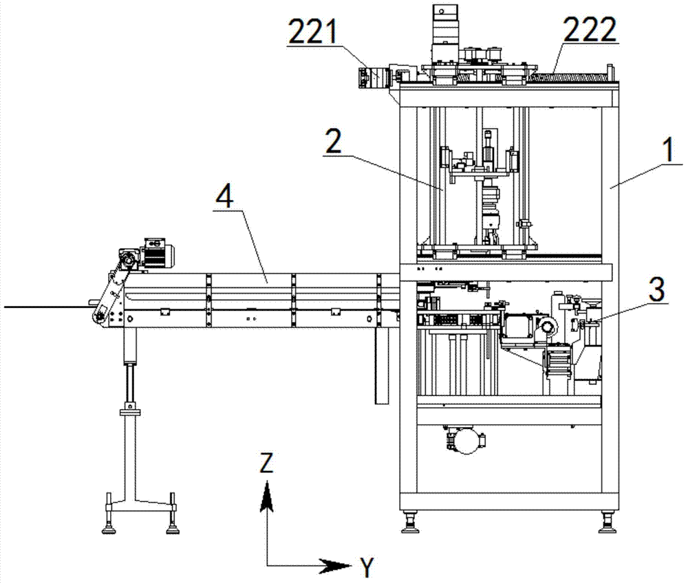
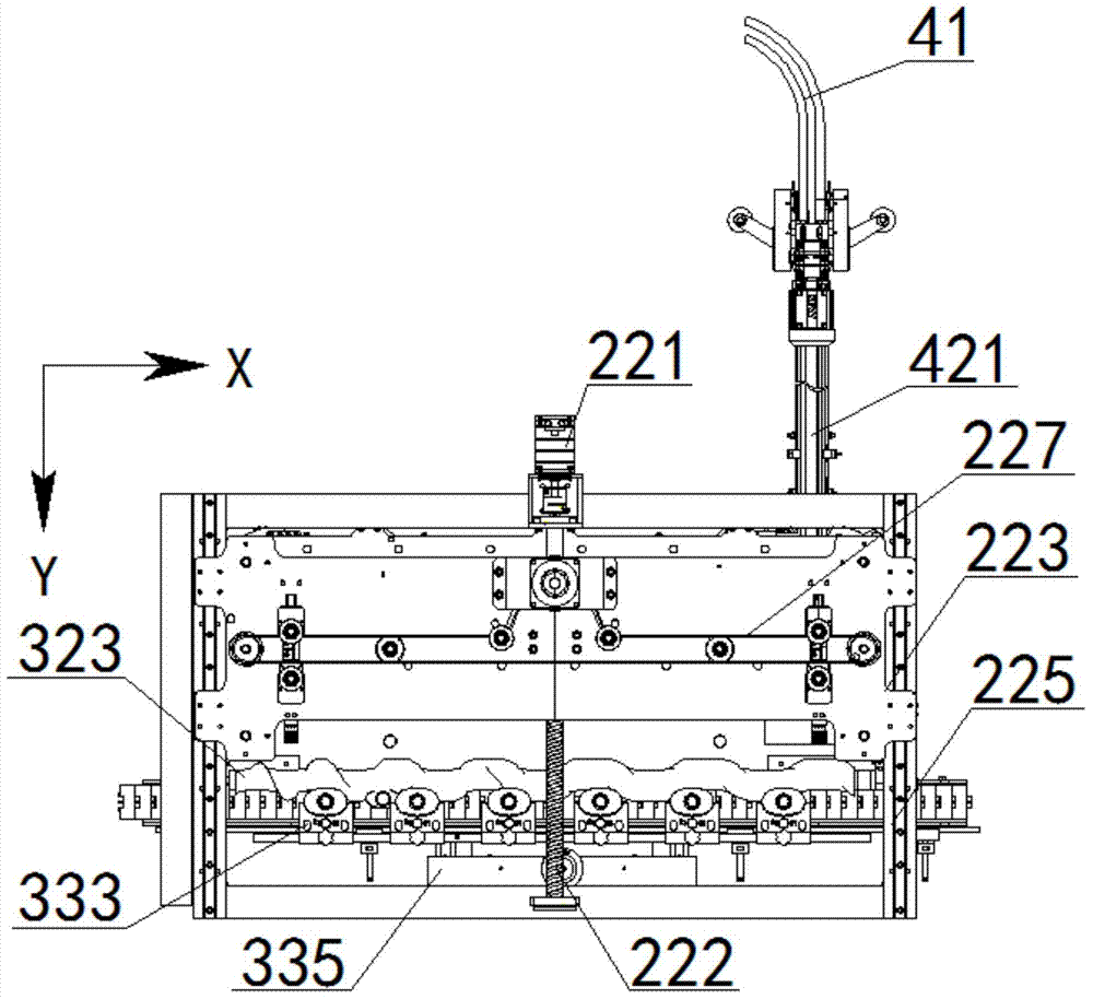
[0041] see Figure 1 to Figure 4 , The in-line capping machine of this embodiment includes a frame 1, and a capping main part 2, a bottle conveying part 3, and a cap feeding part 4 installed on the frame 1. The bottle body conveying part 3 and the cap feeding part 4 are arranged below the capping main part 2, and the bottle body conveying part 3 is arranged in front of the cap feeding part 4.

[0042] see Figure 5 with Image 6 , The capping main component 2 includes a capping head displacement drive assembly 22, a capping head assembly 23 and a clamping jaw assembly 24. The capping head displacement drive assembly 22 is installed on the upper part of the frame 1. The capping head assembly 23 is installed on the capping head displacement driving assembly 22, and there are a plurality of them. The capping head displacement driving assembly 22 drives the capping head assembly 23 to move back and forth and up and down. The jaw assembly 24 is installed at the bottom of the cappin...


PUM


Abstract

The invention discloses an in-line arrangement cap screwing machine. The in-line arrangement cap screwing machine comprises a machine frame, a main cap screwing part, a bottle body conveying part and a cap conveying part, wherein the main cap screwing part, the bottle body conveying part and the cap conveying part are arranged on the machine frame. The main cap screwing part comprises a cap screwing head displacement driving assembly, a plurality of cap screwing head assemblies and a clamping jaw assembly. The cap screwing head displacement driving assembly is arranged at the upper portion of the machine frame, the cap screwing head assemblies are arranged on the cap screwing head displacement driving assembly, and the clamping jaw assembly is arranged at the bottom of the cap screwing head displacement driving assembly. For the main cap screwing part, the clamping jaw assembly is arranged at the bottom of the cap screwing displacement driving assembly, and straws of bottle caps are clamped through pneumatic clamping jaws, so that the bottle caps always keep a vertical state in the lifting process, the shortcoming that the bottle caps themselves possibly curve is overcome, it is ensured that the straw of each bottle cap can be accurately inserted into a bottle body, and cap screwing can be smoothly conducted.

Description

Technical field [0001] The invention relates to an in-line capping machine. Background technique [0002] The in-line capping machine is a machine that can screw the cap on the bottle body. It is suitable for capping different bottle caps in the food, pharmaceutical, daily chemical, pesticide, cosmetic and other industries. [0003] For pump head caps, spray gun caps, spray caps and other bottle caps with straws, the straws of each cap are not necessarily straight down, and some may be bent. Therefore, before screwing the cap, the bottle The straw of the cap may not be accurately inserted into the bottle body, which will eventually cause the capping failure of the in-line capping machine. And because the in-line capping machine is equipped with multiple capping stations to realize simultaneous capping, it is required that after a specified number of bottles enter the in-line capping machine, they can reach an accurate working position and be fixed. It is required that the cap fee...

Claims


Application Information

Patent Timeline
Patent Type & Authority Patents(China)
IPC IPC(8): B67B3/00B65G47/28B65G43/08B65G47/06B65G17/12
Inventor 刘伟徐根宝李明张文明
Owner 江苏汤姆森智能装备有限公司
Learn More