Micro-pore aerator

A technology of microporous aerator and aeration, applied in water aeration, chemical instruments and methods, sustainable biological treatment, etc. Realize the uniform and automatic opening of each annular filter, achieve good automatic cleaning effect, reduce production cost, and good cleaning effect

Inactive Publication Date: 2014-04-30
普民环保科技有限公司
View PDF4 Cites 4 Cited by
  • Summary
  • Abstract
  • Description
  • Claims
  • Application Information

AI Technical Summary

Problems solved by technology

This mechanism has the function of automatic cleaning, and has a good effect on gas dispersion, but the following disadvantages have been found in long-term use: 1) There are many ring-shaped filter pieces and th

Method used


Image

  • Micro-pore aerator
  • Micro-pore aerator
  • Micro-pore aerator

Examples


Embodiment Construction

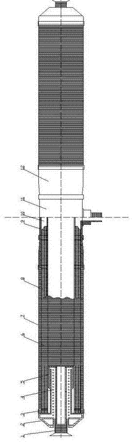
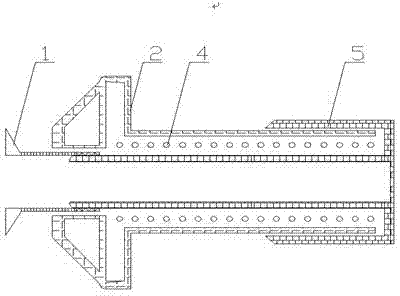
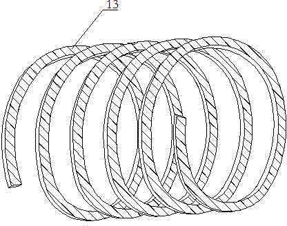
[0010] The specific implementation manners of the present invention will be described below in conjunction with the accompanying drawings. The invention discloses a spiral membrane aerator, which comprises an aeration part, a pressure regulating system, a support part and a connection part, and the aeration part is installed on the support part. The aeration part is a rectangular strip with a certain thickness, which is wound according to a constant diameter to form a spiral diaphragm 7, and each circle is tightly fitted without gaps. A groove 13 on the spiral diaphragm is arranged on one side of the spiral diaphragm 7 . The supporting parts are hollow multi-peak tube 8 and peak tube bracket 9. The aeration part is installed on the multi-peak tube 8, and the spiral diaphragm 7 is supported by the multi-peak tube 8. The wave peaks form an air chamber, which can divide the gas into several part, distribute air evenly.

[0011] In this embodiment, there are two helical diaphrag...


PUM


Abstract

The invention discloses a micro-pore aerator which comprises aeration components, a pressure adjusting system, a support component and a connecting component, wherein the aeration components are arranged on the support component; the aeration components are spiral membrane sheets; the spiral membrane sheets are uniformly wound on the support component; grooves are formed in the spiral membrane sheets. The micro pore aerator is simple in structure, good in automatic washing effect, convenient to mount, efficient and energy-saving, and the production cost is effectively lowered.

Description

technical field [0001] The invention relates to the technical field of sewage treatment, in particular to a microporous aerator. Background technique [0002] In the water treatment industry, the activated sludge process is one of the most widely used processes. The aeration equipment is the key equipment of this process. Its function is to stir the mixed liquid to make the mud and water fully contact and supply oxygen to the microorganisms. Microporous aerators are widely used due to their high oxygen utilization. For example, the gas dispersing device disclosed in the invention patent application with the publication number CN102381751 includes a support mechanism and a gas dispersing mechanism. The gas dispersing mechanism is located on the supporting mechanism. The mechanism communicates with the air inlet, and at least one end surface of the ring-shaped filter has a groove through the inner and outer rings. The annular filter in this mechanism is superimposed under th...

Claims


Application Information

Patent Timeline
IPC IPC(8): C02F3/12C02F7/00
CPCY02W10/10
Inventor 陆新民王丽媛
Owner 普民环保科技有限公司
Why Eureka
Try Eureka