Temporary advanced support device

A kind of advanced support and temporary technology, applied in pillars/supports, mining equipment, earthwork drilling and other directions, can solve the problems of high labor intensity, collapse and collapse of the blasting face, and many workers, so as to achieve a small occupation space, Easy to install and easy to move

Inactive Publication Date: 2014-04-30
CHINA UNIV OF MINING & TECH
View PDF7 Cites 20 Cited by
  • Summary
  • Abstract
  • Description
  • Claims
  • Application Information

AI Technical Summary

Problems solved by technology

First, it is inconvenient to erect and remove support devices, except for wooden pillars (rarely used now)
Because most of them are used in conjunction with metal hinged roof beams and single hydraulic props, it will take a lot of time to install the hinged beams, and it cannot be used when there are geological structures and roof fluctuations, and it is easy to collapse. The surface is easily knocked down and damaged by the cutting head of the roadheader, which also restricts production
Second, because the individual pillars of the device used in conjunction with the pillars are not working with synchronous hydraulic cylinders, when they are hinged together for use, each pillar must have a worker to inject liquid at the same time when the pillar is raised, so more workers are required, and the operation requirements strict
Third, the temporary support is bulky, cumbersome, consumes a lot of materials, and requires a lot of man-hours when moving forward, with many personnel and high labor intensity, which affects the progress of rock loading and roadway excavation
Fourth, for point column support, first, the support area is small, and the exposed rock mass cannot be fully supported, and there is a phenomenon of roof leakage; second, the single support cannot form a joint support, and it is easy to fall under pressure; The blasting face is prone to blasting and collapsing

Method used


Image

  • Temporary advanced support device
  • Temporary advanced support device
  • Temporary advanced support device

Examples


Embodiment Construction

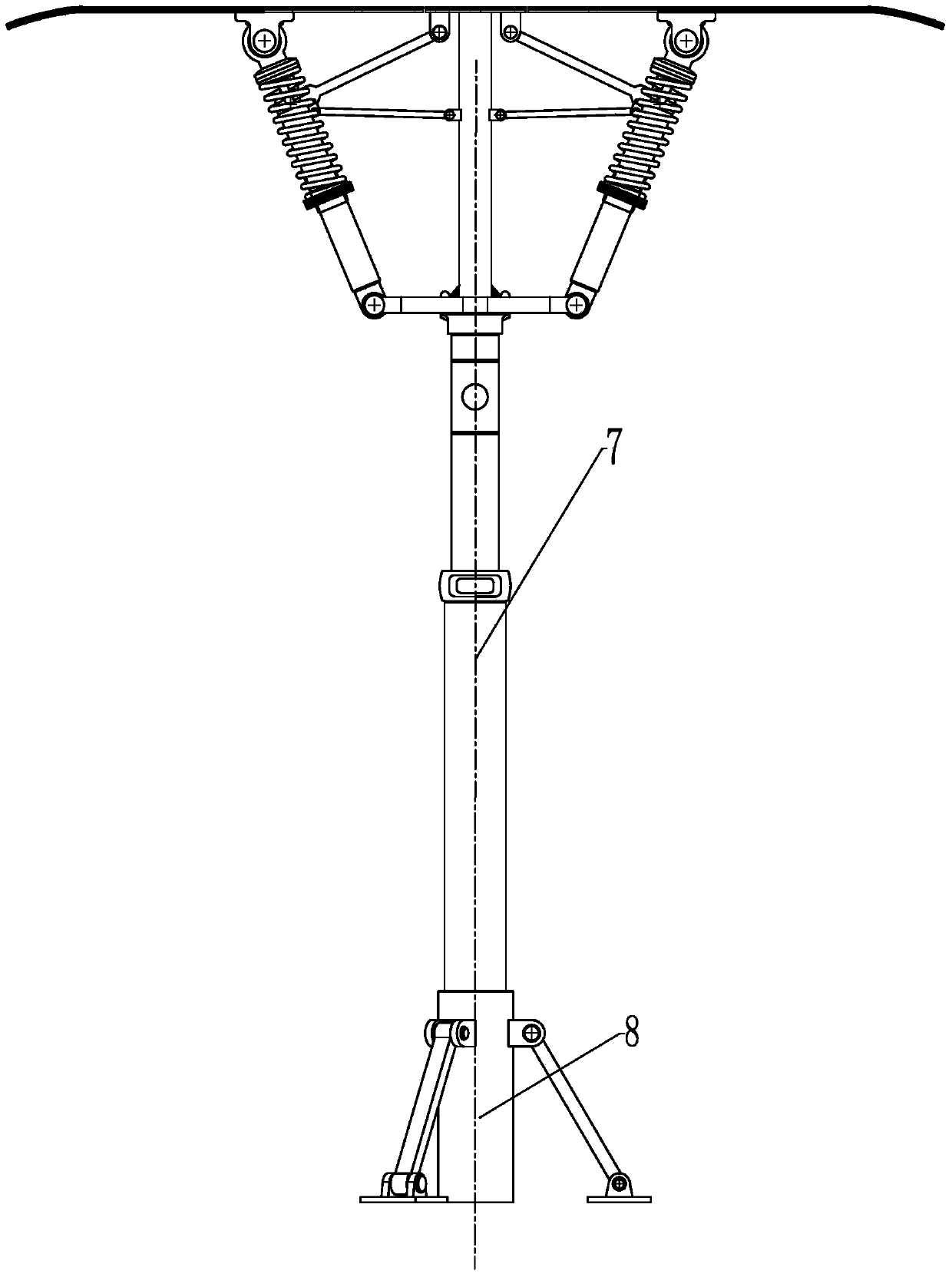
[0028] like figure 1 , figure 2 The embodiment shown is a temporary advance support device, which includes a single hydraulic prop 7, and the top cover of the single hydraulic prop 7 is equipped with an expanded top beam, which is mainly composed of a frame 1, an upper link 2. A linkage mechanism composed of roof beam frame 3, support rod 4, support frame 5 and lower link 6. The upper link 2, roof beam frame 3, support rod 4 and lower link 6 are formed along the support frame 5. The central axis is symmetrically arranged in pairs.

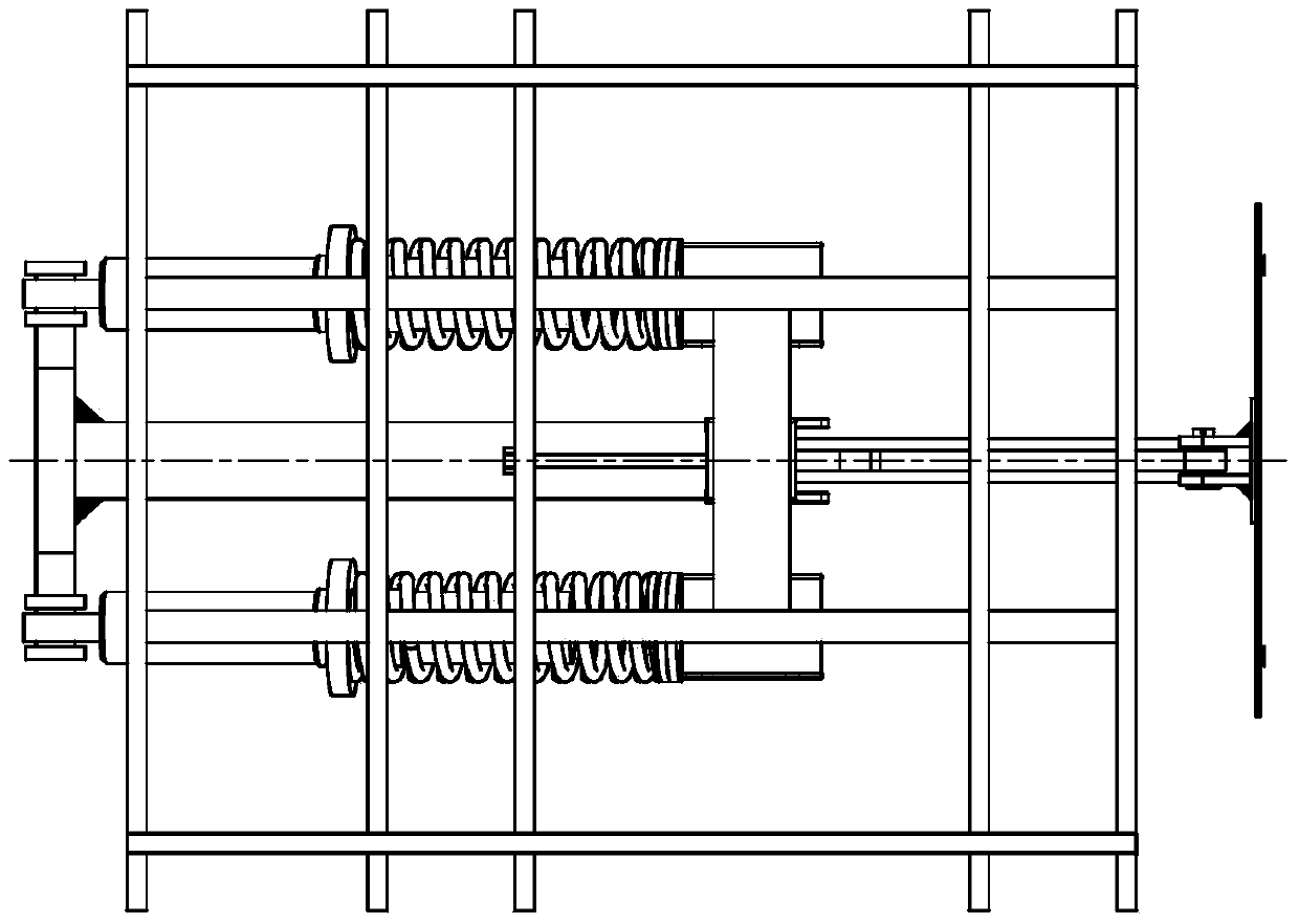
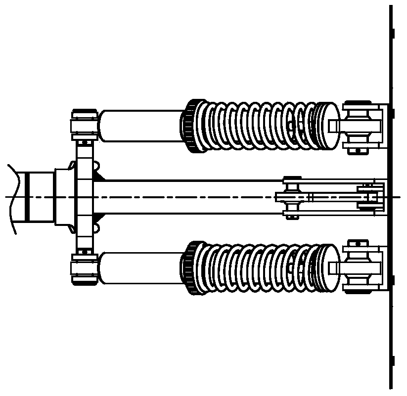
[0029] like figure 2 , image 3 , Figure 4 , Figure 5 As shown, a support rod 5-1 is fixed in the middle of the support frame 5, a connecting rod 3-1 is fixedly connected to the top beam frame 3, and a pair of The upper link 2 mentioned above, the lower end of the upper link 2 is at the hinge point b Hinge described connecting rod 3-1, the upper end of described support rod 4 is at hinge point c Hinged on the top beam frame 3, the lower...


PUM


Abstract

The invention discloses a temporary advanced support device, and belongs to the technical field of mine support. The device comprises a single hydraulic supporting column and an expanding top beam, wherein the expanding top beam is a connecting rod mechanism mainly composed of a machine frame, upper connecting rods, a top beam frame, supporting rods, a supporting frame and lower connecting rods, the middle of the supporting frame is fixedly provided with a supporting base rod, the top beam frame is provided with a connecting rod, the lower portion of the machine frame is symmetrically provided with a pair of the upper connecting rods in a hinged mode, the lower ends of the upper connecting rods are hinged to the connecting rod at hinging points b, the upper ends of the supporting rods are hinged to the top beam frame at hinging points c, the lower ends of the supporting rods are hinged to the supporting frame at hinging points d, one end of each lower connecting rod is hinged to the corresponding upper connecting rod, the other end of each lower connecting rod is hinged to the supporting base rod, and front projections of the hinging points c, the hinging points b and the hinging points d are on the same inclined line when the top beam is completely expanded. The temporary advanced support device is easy to operate, large in support coverage area and convenient to retract, expand and support, and the weight of the product is reduced.

Description

technical field [0001] The invention relates to a temporary advance roof support device suitable for blasting working faces, and belongs to the technical field of mine support equipment. Background technique [0002] There will be problems in the blasting working face when there is no temporary support during the operation after the blasting, and the safety of the staff will be threatened by the fall of gangue and the fall of the roof. Drilling and blasting in the next process. Article 41 of the "Coal Mine Safety Regulations" on roadway support stipulates that empty top operations are strictly prohibited on the excavation face. The support within 10 meters close to the excavation face must be strengthened before blasting. Blasting collapsed and collapsed supports must be repaired before entering the working face for operation. When repairing the bracket, the top and side must be checked first, and it should be carried out one by one from the outside to the inside. [000...

Claims


Application Information

Patent Timeline
Patent Type & Authority Applications(China)
IPC IPC(8): E21D15/00E21D15/44
Inventor 程志红王月宏李武壮牛辉周春华蔡丽华佟哲刘鑫
Owner CHINA UNIV OF MINING & TECH
Why Eureka
Try Eureka