Multi-cylinder circumferentially arranged pulsator direct shaft power plant

A power device and direct shaft technology, applied in the power field, can solve the problems of scattered engine layout, large volume, and complex transmission, and achieve the effects of weight reduction, small volume, and simple transmission

Active Publication Date: 2016-05-04
陆友玲
View PDF6 Cites 0 Cited by
  • Summary
  • Abstract
  • Description
  • Claims
  • Application Information

AI Technical Summary

Problems solved by technology

[0002] At present, the power generated by the combustion of fuel in the cylinder of the general engine is transmitted to the crankshaft through the piston and the piston connecting rod, and then the torque is output externally. The switch of the intake and exhaust valves is also driven by a special intake and exhaust valve transmission mechanism. Due to the arrangement and installation of the cylinder along one or both sides of the long crankshaft and the arrangement of the intake and exhaust valve drives, the layout of the engine is scattered, the volume is large, and the transmission is relatively complicated.

Method used


Image

  • Multi-cylinder circumferentially arranged pulsator direct shaft power plant
  • Multi-cylinder circumferentially arranged pulsator direct shaft power plant
  • Multi-cylinder circumferentially arranged pulsator direct shaft power plant

Examples


Embodiment Construction

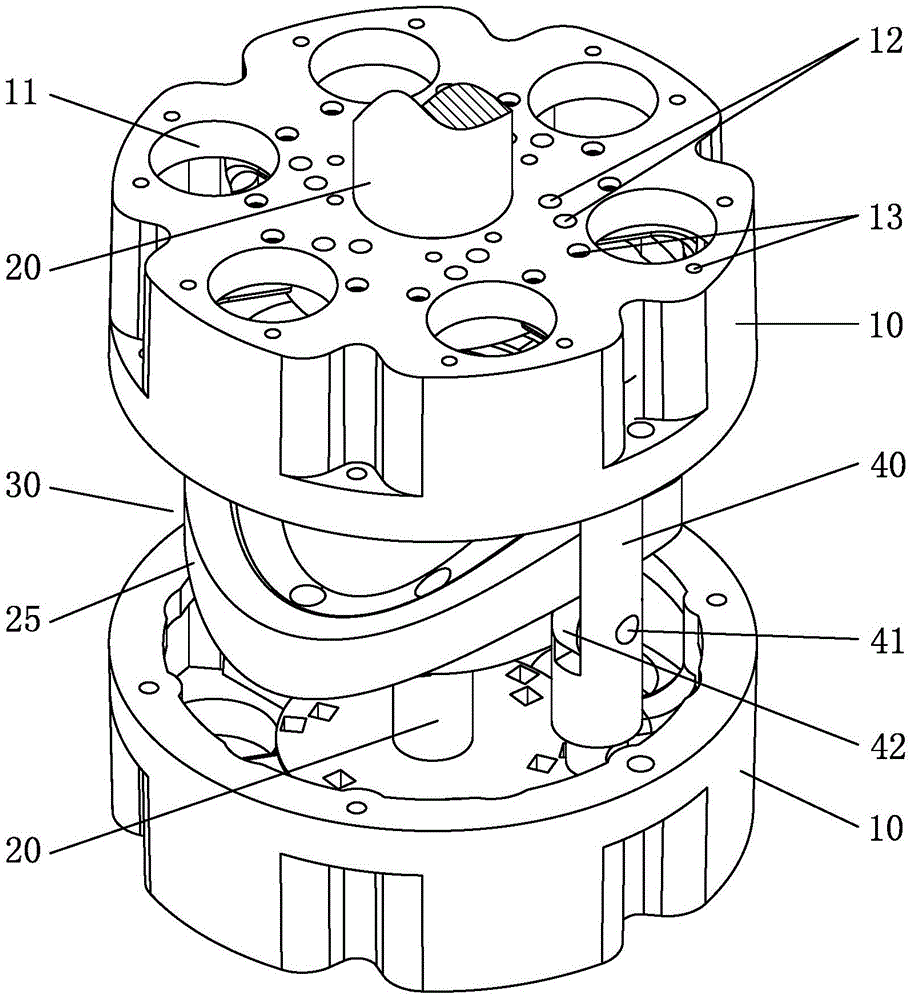
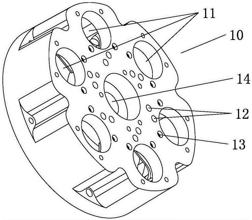
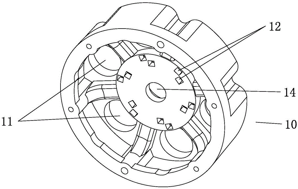
[0036] Below in conjunction with accompanying drawing, the present invention will be further described with specific embodiment, see figure 1 — Figure 9 :

[0037] The multi-cylinder circumferentially arranged pulsator direct shaft power device, the pulsator 30 with the circular track 25 is fixed on the direct shaft 20, and the circular track 25 is two sections of raised tracks 31 symmetrically arranged and connected with two sections of convex tracks. The concave track 32 arranged at intervals from the starting track 31, and more than one connecting rod 40 parallel to the straight axis are evenly distributed around the circumferential interval of the annular track 35, and the outer end of each connecting rod 40 is connected with a piston 44, and each piston 44 are arranged in respective cylinders 43, and the linear reciprocating motion of the connecting rod 40 parallel to the axis of the straight shaft drives the straight shaft 20 to rotate in one direction through the circ...


PUM


Abstract

The invention belongs to the technical field of power units and relates to a pulsator and straight shaft power unit. A pulsator with a circular rail is fixed on a straight shaft. The circular rail comprises two symmetric convex rails and two concave rails; all rails are arranged at intervals; more than mutually parallel links are evenly arranged on the periphery of the circular rail. The outer end of each link is connected with a piston; each piston is disposed in a respective cylinder; the outer end of each cylinder is provided with a cylinder cover which is provided with an exhaust valve and an injection igniter. Ejector rods driven by a slide way of the pulsator and opening intake and exhaust valves in real time are disposed between the pulsator and the cylinder covers. The links are driven to linearly reciprocate parallel to the axis of the straight shaft, in such a manner that the circular rail drives the straight shaft to rotate in one direction. The pulsator and straight shaft power unit has the advantages that the cylinders and pistons arranged circularly around the pulsator are connected to and drive the straight shaft to rotate, the overall structure is accordingly compact, the size is small, the structure is simple, transmission is simple, and the pulsator and straight shaft power unit is applicable to multi-cylinder engines or compressors.

Description

technical field [0001] The invention belongs to the technical field of power, in particular to a pulsator straight-axis power device with multiple cylinders arranged in the circumferential direction. Background technique [0002] At present, the power generated by the combustion of fuel in the cylinder of the general engine is transmitted to the crankshaft through the piston and the piston connecting rod, and then the torque is output externally. The switch of the intake and exhaust valves is also driven by a special intake and exhaust valve transmission mechanism. Because the cylinders are installed along one side or both sides of the long crankshaft and the intake and exhaust valve drives are installed, the layout of the engine is scattered, the volume is large, and the transmission is relatively complicated. Contents of the invention [0003] The object of the present invention is to provide a multi-cylinder circumferentially arranged pulsator direct shaft power device ...

Claims


Application Information

Patent Timeline
Patent Type & Authority Patents(China)
IPC IPC(8): F02B75/26F02B75/32
Inventor 陆友玲
Owner 陆友玲
Why Eureka
Try Eureka