Multistage speed changing device

A technology of speed change mechanism and tower gear, applied in the direction of transmission device, transmission device parts, gear transmission device, etc., can solve the problems of high technical requirements for manufacturing and maintenance, complex structure of speed change mechanism, inconvenient operation, etc., to reduce the complexity of assembly process and Technical, outstanding substantive features, easy to control effect

Inactive Publication Date: 2014-04-30
胥祥朋
View PDF9 Cites 7 Cited by
  • Summary
  • Abstract
  • Description
  • Claims
  • Application Information

AI Technical Summary

Problems solved by technology

[0002] At present, various gear transmission mechanisms and devices generally use gears to move along their axial direction to realize the meshing and separation of gears, so as to realize the adjustment of different transmission ratios, such as At present, the gear shifting devices on ships, vehicles and other transportation machinery all use the above-mentioned gear shifting device. The above-mentioned device has the defects of complex structure, inconvenient operation, large volume and high cost.
[0003]Multi-stage transmission mechanism can also adopt planetary gear structure, most planetary gear structures use actuators to make planetary gears in different meshing states to obtain different transmission ratios, The structure of the planetary gear used to achieve the above purpose needs to be composed of multiple planetary rows and numerous shift actuators, which makes the structure of the transmission mechanism complicated and requires high technical requirements for manufacturing and maintenance. This is the deficiency of the existing technology.

Method used


Image

  • Multistage speed changing device
  • Multistage speed changing device
  • Multistage speed changing device

Examples


Embodiment Construction

[0032] In order to clearly illustrate the technical characteristics of this solution, the following will describe this solution through specific implementation modes and in conjunction with the accompanying drawings.

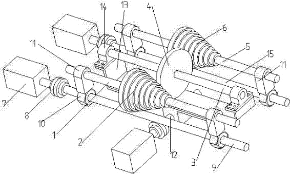
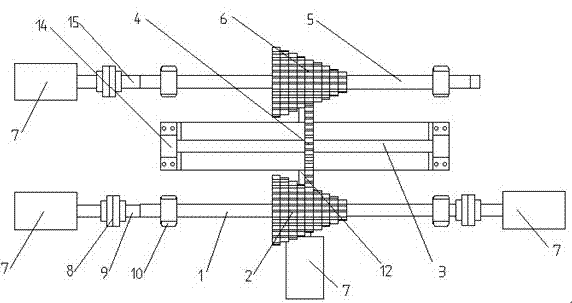
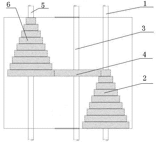
[0033] Such as figure 1 and figure 2 Shown: a multi-stage transmission mechanism, which includes a power input shaft 1, an intermediate transmission body and a power output shaft 5, the power input shaft 1 is provided with a driving tower gear 2, and the power output shaft 5 is provided with a The driving tower gear 2 is matched with the driven tower gear 6 , and one driving gear in the driving tower gear 2 meshes with a corresponding driven gear in the driven tower gear 6 through an intermediate transmission body for transmission.

[0034] The above-mentioned intermediate transmission body includes a radially movable transmission shaft 3 on which a transmission gear 4 is arranged, and the axes of the power input shaft 1 , transmission shaft 3 and power output...


PUM


Abstract

The invention relates to the technical field of mechanical transmission, in particular to a multistage speed changing device. The multistage speed changing device comprises a power input shaft, a middle transmission body and a power output shaft, wherein a driving stepped gear is arranged on the power input shaft, a driven stepped gear matched with the driving stepped gear is arranged on the power output shaft, and one driving gear in the driving stepped gear is in meshing transmission with one corresponding driven gear in the driven stepped gear through the middle transmission body. The middle transmission body comprises a transmission shaft capable of radially moving, wherein a transmission gear is fixedly connected onto the transmission shaft, and the axes of the power input shaft, the transmission shaft and the power output shaft are parallel. The multistage speed changing device is simple in structure, stable in transmission and convenient to control.

Description

technical field [0001] The invention relates to the technical field of mechanical transmission, in particular to a multi-stage transmission mechanism. Background technique [0002] At present, various gear transmission mechanisms and devices generally use gears to move along their axial direction to realize the meshing and separation of gears, so as to realize the adjustment of different transmission ratios. The gear transmission device with the above structure has the defects of complicated structure, inconvenient operation, large volume and high cost. [0003] The multi-stage transmission mechanism can also adopt a planetary gear structure. Most planetary gear structures use the actuator to make the planetary gears in different meshing states to obtain different transmission ratios. The structure of the planetary gears used to achieve the above purpose needs to be multi- Composed of a planetary row and many shift actuators, the structure of the transmission mechanis...

Claims


Application Information

Patent Timeline
Patent Type & Authority Applications(China)
IPC IPC(8): F16H3/32F16H57/023
CPCF16H3/32F16H55/17F16H57/023
Inventor 胥祥朋
Owner 胥祥朋
Why Eureka
Try Eureka